Home > Gearmotor Handbook > AC Induction Gearmotors & Motors
AC Induction Gearmotors & Motors
Although commutator and brush assemblies may be used in some types of alternating current (AC) gearmotors and motors (series/universal wound), brushless induction-type designs are by far the most common and most reliable for industrial AC motors and gearmotors that operate from an AC power source or from an AC control (adjustable speed drive).
AC Motor Action
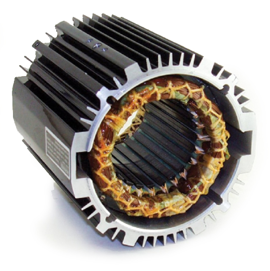
In an AC induction motor or gearmotor, the stator winding sets up a magnetic field which reacts with the current-carrying conductors of the rotor to produce rotational torques. The rotor currents are induced in the rotor conductors by the stator’s changing magnetic field, rather than by means of a commutator and brushes. This induction action is the central operating principle of AC induction motors.
AC power is commercially supplied in both single-phase and three-phase forms. The essential operating characteristics of AC induction motors and gearmotors will vary according to:
- winding types (split-phase, shaded-pole, three-phase, etc.), and
- the number of phases, the frequency, and the voltage of the power source.
Polyphase Motors (Two or Three Phases)
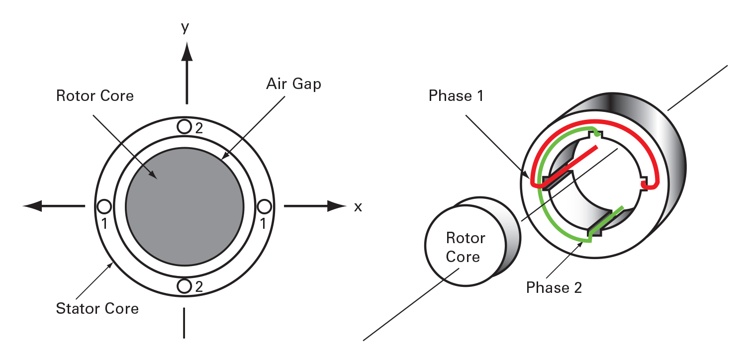
The production of a rotating magnetic field can be simply illustrated by considering a two-phase motor with two embedded stator windings for establishing the magnetic fields. Each coil, for simplicity, shall consist of a single loop of wire connected to one phase of a two-phase AC supply. We shall refer to the coil supplied by phase 1 current as Coil 1, and the coil supplied by phase 2 current as Coil 2. The two coils are placed at a right angle to each other in the stator core, with each coil creating a two-pole field. See Fig. 2-1.
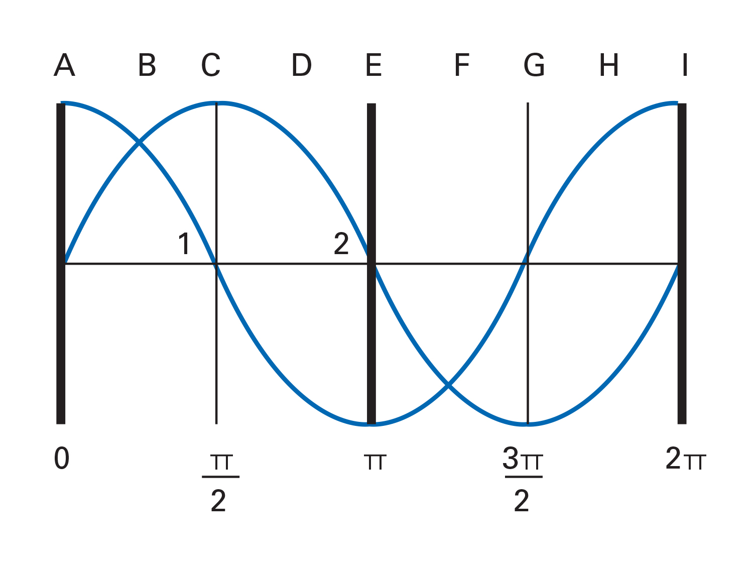
The output waveform of the two-phase AC supply is represented in Fig. 2-2. The voltage in each phase varies sinusoidally in time and one lags the other by π/2 radians or 90° (electrical). Note: one complete cycle = 2π radians or 360° (electrical).
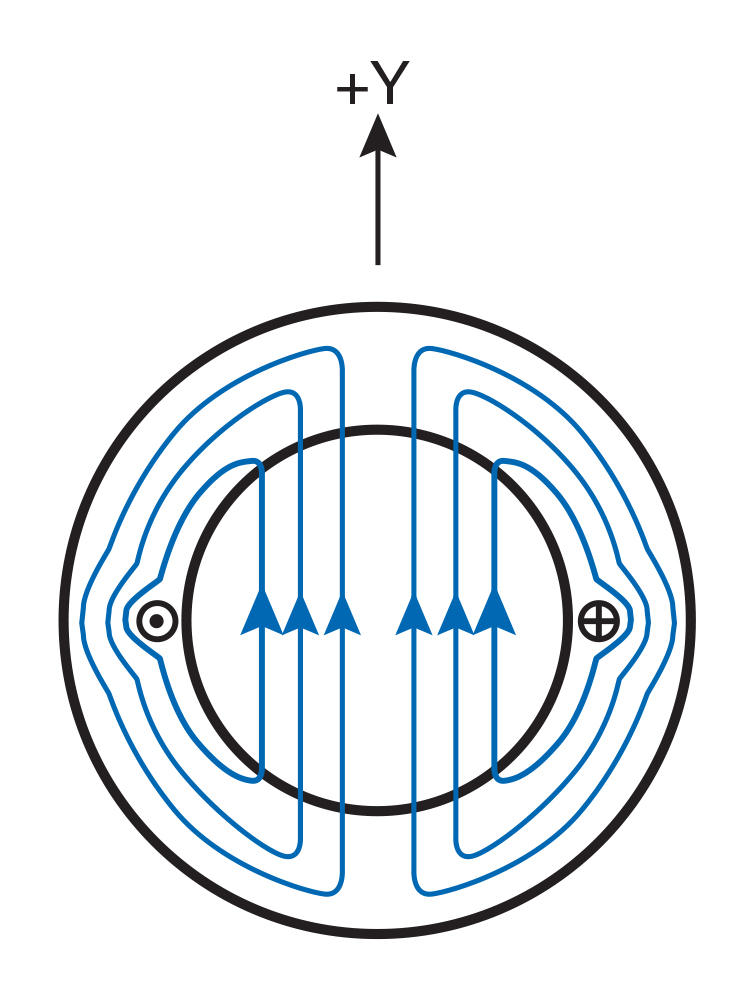
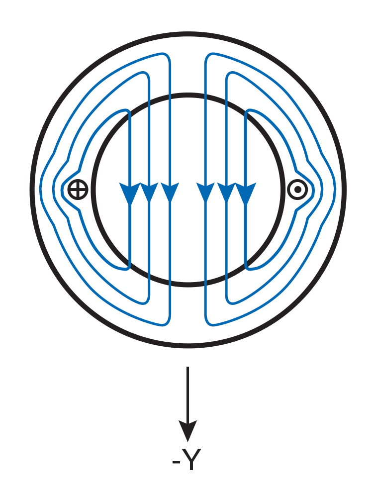
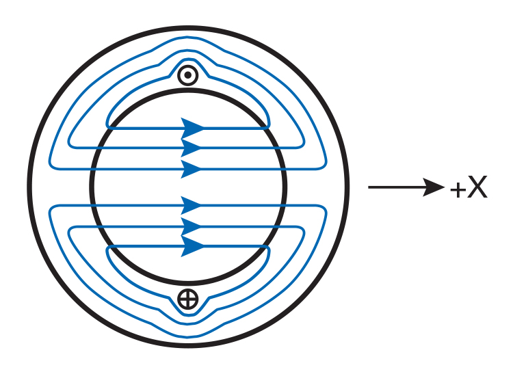
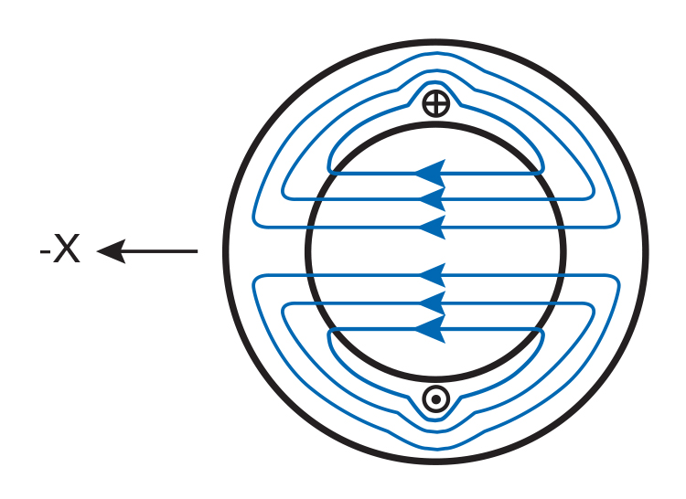
Let us first consider Coil 1 only. When the phase 1 current is in its positive portion of the cycle (current enters Coil 1 from the right and exits on the left), a magnetic field is set up which points in the positive (+Y) direction. See Fig. 2-3. When the current flows in the opposite direction during the negative portion of its cycle, the magnetic field points in the negative (-Y) direction. See Fig. 2-4. Since the strength of the magnetic field (H) is proportional to the amount of current flowing through the coil, the field strength also oscillates sinusoidally in time.
Similarly, we can illustrate in Figs. 2-5a and 2-5b the magnetic field due to current flowing in Coil 2.
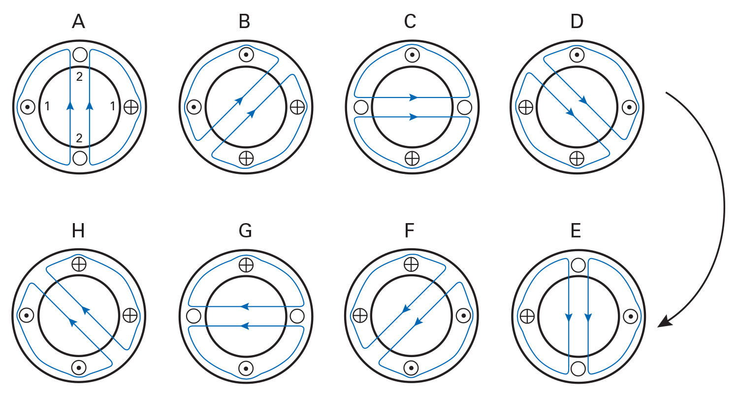
Now we have two perpendicular fields. Each varies sinusoidally in time, and one lags the other by π/2 radians. The combined effect (vector sum) of the two fields is a rotating resultant field. Figure 2-6 illustrates the progression of the rotation at eight different points in time. The letters (A-H) in Fig. 2-6 correspond to the points (A-H) on the waveform diagram in Fig. 2-2.
It can also be shown mathematically that the magnetic field rotates. If we choose the center of the stator as our reference point, we can define BY and BX as the magnitudes of the magnetic flux densities due to the currents flowing through Coil 1 and Coil 2 respectively. Both BY and BX are functions of their respective currents* and are functions of time. (*Note: This assumes a constant permeability in the ferromagnetic structure). Also, due to symmetry, their peak values are the same.
Since BY and BX vary sinusoidally with their corresponding currents we can express them in the following equations:
BY = COS (2π ft)
BX = SIN (2π ft)
Where:
B = peak value of either BY or BX f = frequency of the supply current (cycles/unit time) t = time
Let Br be the resultant value of BY and BX and let Θ be the angle of Br with respect to the axis as shown in Fig. 2-7. For example:
| tanΘ = | B SIN (2π ft) | = tan (2π ft) |
| B COS (2π ft) |
or
Θ = (2π ft)
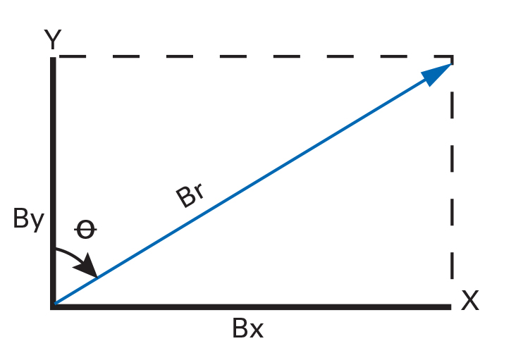
Hence, Θ is increasing at a rate of 2π f radians per unit time. In other words, Br is rotating with the same frequency as the supply current. We can also show that the magnitude of Br remains constant during rotation, since:
Br2 = BY2 + BX2
Since B is independent of time, the magnitude of the rotating resultant field (Br) is constant.
We have demonstrated that a rotating magnetic field is generated in a two-phase stator. These basic analyses can be extended to a three-phase stator and show that it also has a rotating field. Therefore, we will not go into detail with three-phase stators.
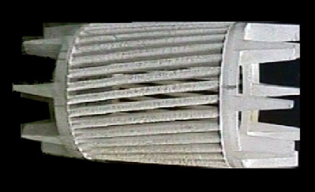
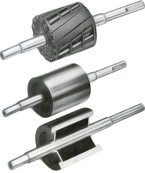
The rotor of a typical AC induction motor is constructed from a series of steel laminations, each punched with slots or holes along its periphery. When laminations are stacked together and riveted, these holes form channels which are filled with a conductive material (usually aluminum, but also copper in newer high-efficiency designs) and short-circuited to each other by means of conducting end rings. The conductors are typically formed by die-casting.
This one-piece rotor casting can also include integral fan blades which create a built-in cooling device (for open design AC motors). The common term for this type of rotor is “squirrel cage” (because of its resemblance to the runway of an old-fashioned squirrel cage or hamster wheel). It is an inexpensive and common type of AC induction motor rotor design. See Fig. 2-8.
As the rotating field sweeps past the bars in the rotor, an induced current is developed. Since the flow of current in a conductor sets up a magnetic field with a corresponding polarity, an attraction will result between the rotating magnetic field of the stator and the induced field in the rotor. Rotation results from the motor’s attempt to keep up with the rotating magnetic field. The rate of change at which the lines of flux cut the rotor determines the voltage induced. When the rotor is stationary, this voltage is at its maximum. As rotor speed increases, the current and corresponding torque decreases. At the point of synchronous speed (speed of the rotating field), the induced current and developed torque both equal zero.
The rotor in a non-synchronous AC induction motor will always operate at some speed less than synchronous unless it is aided by some supplementary driving device. This lag of the rotor behind the rotating magnetic field is called “slip”, and is expressed as a percentage of synchronous speed: (RPM = revolutions per minute)
| % Slip = | synchronous speed - actual speed | x 100 |
| synchronous speed |
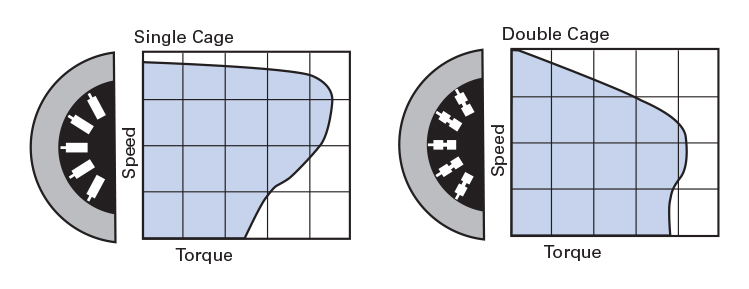
In designing rotors for induction motors, the shape and dimensions of the slots have a demonstrable effect on the performance characteristics of the motor. This variation is illustrated in Fig. 2-9.
Another design factor common to most squirrel cage induction rotors is the deliberate “skewing” of the slots (positioning the slots at a slight angle to the shaft) to avoid cogging action and wide variations in starting torque which may result when bars are placed parallel to the stator slots.
Inverter-Duty, Three-Phase Motors / Gearmotors
Variable Speed, Three-Phase Gearmotors, Motors and matching Speed Controls
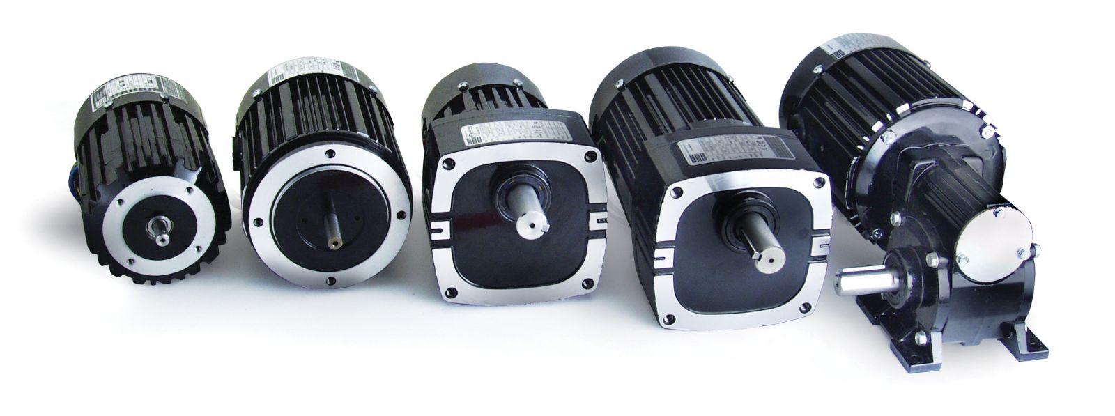
Bodine Electric’s Pacesetter™, variable-speed AC three-phase motors and gearmotors are rated from 1/25 - 3/4 HP, 230 VAC or 230/460 VAC, 60 Hz. All feature Bodine’s Quintsulation™ 5-stage insulation system, which meets NEMA MG 1-1993, Section IV, Part 31. This insulation protects the motor from potential spikes or corona damage caused by the inverter. Pacesetter inverter duty gearmotors are UL recognized for construction and cURus or UR/CSA marked. In addition, these products are in compliance with the Low Voltage Directive “CE”, and all products meet the European RoHS Directive. Most Bodine 34R, 42R and 48R frame inverter duty gearmotors and motors are now available with optional 230/460 VAC, 60 Hz windings.
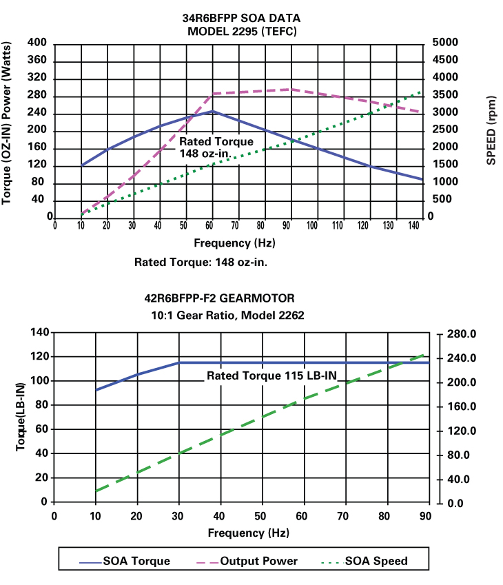
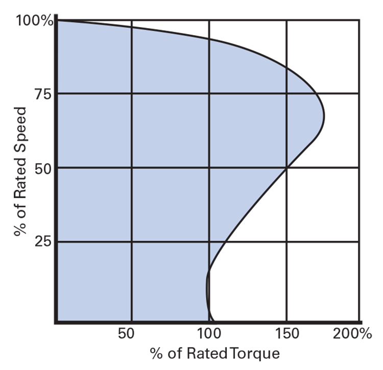
Safe Operating Torque and Speed Area (SOA)
Rated torque is either the value of torque which corresponds to nameplate output power and speed at 60 Hz, or it is the maximum torque at gear strength limits (rated torque can be either motor limited or gear limited). We define SOA Torque as the maximum torque at which the motor still operates within Class F thermal limits, or as the maximum torque of a gearmotor when it is gear-limited. Continuous duty operation must be limited to the area below the SOA or gear-limited torque curves.
The SOA torque for synchronous motors is close to the pull-in torque; that is, the motor will pull out of synchronism if the required torque exceeds the SOA torque. The SOA speed of Bodine’s Pacesetter™ non-synchronous motors is BELOW rated speed. For example, Bodine model 2295, a type 34R6BFPP motor has a rated torque of 148 oz-in. at a rated speed of 1700 rpm (60 Hz), but only a SOA speed of 1572 rpm (60 Hz) at 247 oz-in. SOA torque. The higher SOA torque will be produced at the trade-off of motor speed. Starting currents for standard Pacesetter motors were measured with the motor connected to a three-phase power source. Starting currents may be different when the motors or gearmotors are operated with an inverter drive (VFD/ASD). The SOA Graphs for Bodine Electric inverter duty, three-phrase, AC induction motors and gearmotors were generated by performance-testing all standard models over the full rated speed/frequency range. The SOA graphs provide the data needed to successfully apply these variable speed AC motors and gearmotors.
Benefits: Inverter duty, three-phase gearmotors offer performance improvements over comparable single-phase units. When operated with an AC speed control (inverter), the motor or gearmotor speed can be easily matched to varying application loads. Pacesetter gearmotors and motors are more efficient than their single-phase counterparts, they are more compact, and provide higher output torques in the same size package. In addition, these variable-speed AC gearmotors and motors don’t require brush replacement or brush maintenance, and the gearheads are lubricated for life.
Features:
- Quintsulation™ 5-stage insulation system designed to meet NEMA MG 1-1993, Section IV, Part 31.
- 230VAC or 230/460VAC, 60 Hz, 3-phase for operation with a wide range of inverter products.
- Inverter-Grade magnet wire and Class “F” insulation system for increased protection against spikes and corona damage caused by the inverter.
- UL recognized for construction, CSA certified, and in compliance with the Low Voltage Directive “CE”. Products comply also with the RoHS Directive.
As a true system-solution provider, Bodine Electric Company also offers several new AC speed controls (Variable Frequency Drives or Adjustable Speed Drives), including chassis type (IP-20) and enclosed (NEMA-1, -4 and NEMA-4X). When purchased as a “matched system”, Bodine customers benefit from an extended two-year warranty for the motor or gearmotor and control.
Typical Applications: Conveyor systems, food processing equipment, medical equipment and factory automation.
Single-Phase Motors / Gearmotors
We have demonstrated in the previous section that two-phase and three-phase induction motors will create a rotating magnetic field corresponding to excitation of the stator windings.
In the single-phase induction motor, there is only one phase active during normal running. Although it will pulse with intensity, the field established by the single-phase winding will not rotate. If a squirrel cage rotor were introduced into the air gap between the stator poles of a single-phase motor, it might vibrate intensely but would not initiate rotation. However, the rotor shaft will start to rotate in either direction if given a push.
This rotation sets up an elliptical revolving field which turns in the same direction as the rotor. The “double rotating field theory” and the “cross-field theory” explain why a single-phase motor will rotate if it is started by some means. Due to the complexity of the mathematics involved, they will not be discussed here. What is important to remember is that single-phase AC motors require an auxiliary starting scheme.
Single-Phase AC Motor Types
Single-phase motors, without the aid of a starting device, will have no inherent “starting” torque. To produce torque, some means must be employed to create a rotating field to start the rotor moving. A number of different methods are used. The particular method used determines the “motor type.” An explanation of the various types follows.
Split-Phase (Non-synchronous)
Features:
- Continuous duty
- AC power supply
- Reversibility normally at rest
- Relatively constant speed
- Starting torque 175% and up (of rated torque)
- High starting current (5 to 10 times rated current)
- No run capacitor required
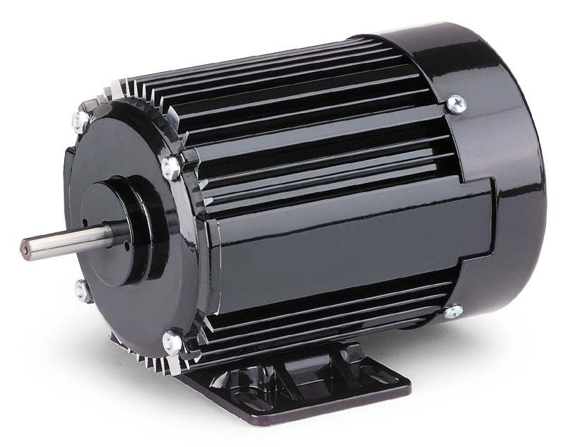
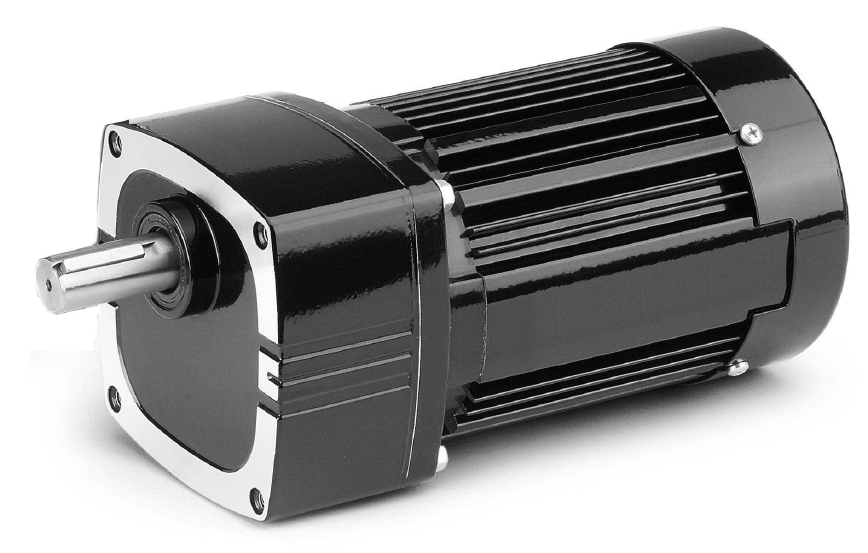
Design and Operation: Split-phase motors are perhaps the most widely used relatively constant speed AC motors (of appreciable output) employed for driving domestic appliances. Also used for a variety of industrial applications, motors of this type are relatively simple in construction and lower in cost than most other types. Low cost, plus good efficiency, starting torque and relatively good output for a given frame size have made the split-phase AC induction motor today’s general purpose drive. See Fig. 2-10.
Split-phase motors are single-phase motors equipped with main and auxiliary windings connected in parallel (during the start cycle). The auxiliary winding shares the same slots as the main winding, but is displaced in space.
To give the design its unique starting characteristic, the auxiliary winding is wound with finer wire and fewer turns (for high resistance and low reactance) than the main winding, and the current flowing through it is substantially in phase with the line voltage. The current flowing through the main windings, because of their lower resistance and higher reactance, will tend to lag behind the line voltage in time. This lagging effect will act to “split” the single-phase of the AC power supply by causing a phase (time) displacement between the currents in the two windings.
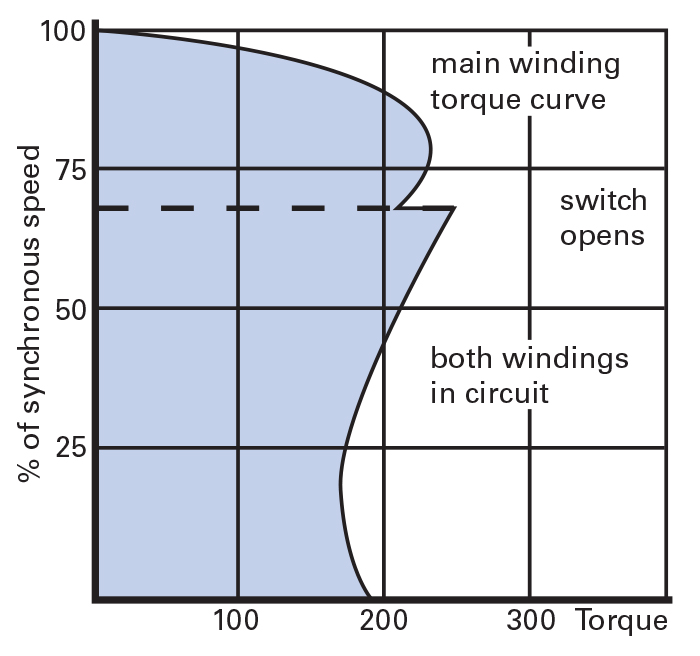
The space and phase displacement of the main and auxiliary windings produce a rotating magnetic field which interacts with the rotor to cause it to start (begin rotating). After the split-phase motor has attained approximately 70% of rated speed, the auxiliary winding is automatically disconnected from the circuit by means of a centrifugal switch or current sensitive relay. The motor will then continue to run on the single oscillating field established by the main winding. See Figs. 2-12 and 2-13.
Advantages: Split-phase motors will operate at relatively constant speed, typically from about 1790 RPM at no load to 1725 or 1700 RPM at full load for a four-pole, 60 Hz motor.
A standard four-wire split-phase motor can be reversed at standstill or while operating at a speed low enough to ensure that the auxiliary winding is in the circuit. Split-phase motors could also be reversed at full speed if a special (external) switching device is used to connect the starting winding in the reverse direction sufficiently long to reverse the motor. This is normally not done because of the risk to burn out the starting winding during a long reversal period. Gearmotors should never be reversed at full speed. To prevent gearing damage, the gearmotor (gear train) should come to a full stop before reversing the direction of rotation!
Perhaps the most important feature associated with split-phase motors is their relatively low initial cost. The high starting torque combined with simple, reliable construction make split-phase AC motors ideal for many general purpose applications. Since the rate at which the motor can be accelerated is often a primary concern to the applications engineer, split-phase designs are often specified because of their ability to come up to speed rapidly (reaching running speeds with normal loads in a fraction of a second). Another benefit of the split-phase motor is that it does not require a run capacitor.
Application Considerations: Because of the high resistance of the starting winding, repeated starting and stopping will heat the windings (in particular, the starting winding) and result in loss of torque and possible winding damage. This is one of the reasons why it is not practical to apply split-phase motors when very frequent starts are required, or where high inertial loads must be accelerated.
Split-phase motors have a high starting current which can range from 5 to 10 times the current drawn while running. If the starting load is heavy, the wiring between the motor and the power source must be of adequate size to prevent excessive voltage drop. The low voltage conditions resulting from inadequate wire size will result in decreased motor starting torque. Frequent starts, coupled with inherent high starting current, can also adversely affect starting switch or relay life.
Cautions: The auxiliary starting winding in a split-phase motor is designed for very short duty. If it stays in the circuit for more than a few seconds, the relatively high starting current, which it draws, can cause overheating of the winding. Should this happen, a more powerful motor or a motor having different electrical characteristics should be considered.
Caution should be used when driving high inertial loads with split-phase motors. This type of load can prolong the acceleration and “hang” too long on the starting winding.
Capacitor Motors and Gearmotors (Non-synchronous)
Features:
- Continuous duty
- AC power supply
- Reversibility (3-wire or 4-wire reversible)
- Relatively constant speed
- Starting torque 75% to 150% of rated torque
- Normal starting current (3 to 7 times rated current)
- Requires a capacitor
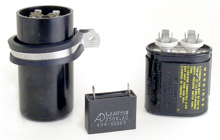
Design and Operation: Capacitor action described in the Bodine Handbook, chapter one, has been found to provide specific performance improvements when used with single-phase AC motors and gearmotors (Fig. 2-14). The types of capacitors (see Fig. 2-15.) used and the method of operation varies with motor type. The operating characteristics of each type are quite different and will be discussed separately. In general, there are three distinct capacitor motor types:
- Capacitor Start (CS) — motors use one capacitor in the starting mode only,
- Permanent Split Capacitor (PSC) — motors may operate with one permanently-connected, continuous-duty AC-type capacitor for both starting and running, and
- Two Capacitor Start/One Capacitor Run — motors use one continuous-duty capacitor and one capacitor in the start mode only, and then switch out the start capacitor while running.
Capacitor Start (CS): The capacitor start motor is essentially a split-phase motor which has two separate windings: a main or, “running” winding and an auxiliary or “starting” winding. However, in the capacitor start motor, a capacitor is added in series with the start winding during the starting mode to increase starting torque and/or reduce starting current. As in the case of the split-phase design, the starting winding and capacitor will be disconnected when the motor has reached approximately 70% of running speed.
Like the conventional split-phase motor, the capacitor start design runs with only the main winding energized. This “run” winding sets up a pulsating magnetic field which interacts with the rotor to develop the necessary running torque and speed. Since the “run” winding alone has no starting capability, both starting and running windings are energized while starting. Because of the high resistance-to-inductance ratio of the “start” winding relative to the “run” winding, the currents in the two windings (when energized) are sufficiently displaced (time wise) from each other to produce a rotating magnetic field and the necessary torque for starting.
The addition of a capacitor, in series with the “start” winding, can significantly enhance the starting characteristics by improving the phase relationship between the “run” and the “start” windings. With the proper selection of capacitor value, the starting torque can be increased and/or the starting current decreased. Of course, capacitor values must be carefully selected to produce this effect. Because the CS motor’s capacitor is used only when starting, its duty cycle is very intermittent. Thus, a relatively small AC electrolytic-type capacitor can be used in CS designs.
Permanent Split Capacitor (PSC): When split-phase or capacitor start (CS) motors are applied in applications that require long or frequent starts, the motor may tend to overheat and adversely affect the system reliability. In this type of application, PSC motors and gearmotors should be considered.
The PSC capacitor winding is permanently connected in series with a continuous-duty “run” capacitor. In contrast to the split-phase or capacitor start motor, the “second” winding is energized at all times.
Permanent split capacitor motors operate in much the same way as two-phase AC motors. The capacitor in the PSC design causes the current in the capacitor winding to be out of phase (with respect to time) with the current in the main winding, thus a rotating magnetic field is created. This action gives the PSC motor greater efficiency and quieter, generally smoother operation than the split-phase or the split-phase capacitor start designs. See Fig. 2-16.
Two Capacitor Start/One Capacitor Run: A variation of the permanent split capacitor design, the two capacitor motor uses one capacitor for starting, in addition to the continuous-duty run capacitor used for both starting and running. The use of two capacitors helps to preserve the efficiency and quietness of the PSC motor while running and produces a corresponding improvement in the starting characteristics. If we increase the value of the capacitor in a PSC motor, we can normally improve starting torque, but at the expense of running performance. However, by using two capacitors (one for running and two in parallel for starting), optimum running and starting characteristics can be obtained.
To understand how this works, it is important to realize that the magnitude of the current flowing in the capacitor winding changes with the speed of the rotor. The value of the current in the capacitor winding is lowest when the rotor is at zero speed, and highest when the rotor speed is at its maximum. A capacitor and capacitor winding combination that is optimized for “locked rotor” or starting conditions will not be optimum for normal running operation. The power input while running will be high, and the current in the capacitor winding will not lead the main current by the ideal 90 degrees, resulting in inefficient operation.
A capacitor and capacitor winding optimized for running will be correspondingly less efficient in the starting mode. The use of two capacitors for starting and one for running overcomes the compromise made in the PSC designs.
Advantages: In addition to the improved starting torque characteristics made possible by the capacitor in the capacitor start split-phase design, the reduction of starting current reduces the effect on other equipment due to line voltage drop encountered with high starting current split-phase designs. Lower starting current will also contribute to longer life and greater reliability in switches and relays.
In general (for a given horsepower rating), although the permanent split capacitor motor is more expensive than split-phase and capacitor start designs, it produces quieter operation and provides the frequent start/stop capability essential in many applications.
Application Considerations: Since the phase angle in PSC motors changes with an increase in load, performance will usually be less satisfactory while starting. In usual design practice, a compromise must therefore be made between the starting and running modes. Changing the capacitor value specified by the manufacturer will affect both running and starting characteristics so that any improvements in starting will usually result in a decrease in running performance.
Cautions: While an optimum capacitor value can enhance motor performance, an improper value of capacitance can decrease performance. It is, therefore, advisable to use the rated capacitor value recommended by the manufacturer (on the motor nameplate). Any change from the rated value is usually detrimental to the design and is not encouraged. When a failed capacitor is replaced, it should always be replaced with a capacitor of equal capacitance and voltage rating. Voltage rating is important for continued reliability and safety.
It should also be noted that PSC motors should be run at or near their rated load points. Unlike other motor types, PSC designs will tend to run hotter if lightly loaded or unloaded.
Shaded Pole Motors (Non-synchronous)
Features:
- Continuous duty
- Low efficiency
- AC power supply
- Relatively constant speed
- Low starting torque (only 50% to 80% of rated torque)
- Low starting current
- Unidirectional (non-reversible)
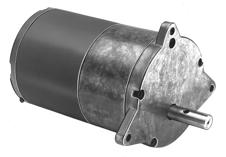
Design and Operation: A simple and economical drive, the shaded pole motor (Fig. 2-17) is used in countless consumer and industrial applications ranging from room air conditioners to advertising displays. Shaded pole motors have no internal switches, brushes or special parts, and therefore offer substancial cost savings in applications requiring relatively constant speed and low power output.
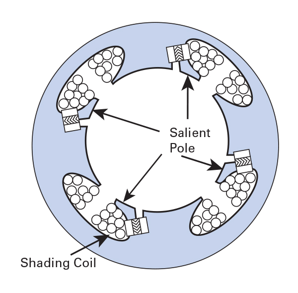
While split-phase motors make use of high resistance auxiliary or "starting" coil wound similar to the main winding, shaded pole designs use an entirely different type of stator lamination which allows for a set of salient poles* surrounded by the main windings. *Note: A motor when its poles are concentrated in relatively confined arcs and the winding is wrapped around these poles (as opposed to distributing the winding in a series of slots).
Salient poles are broad radial projections (equal in number to the number of poles) distributed around the active surface of a rotor or stator and around which windings may be coiled. See Fig. 2-18. These are full pole pitch winding which are fractionally distributed in a series of slots.
Advantages: The shaded pole motor is simple in design and construction, making it readily adaptable to high-volume, low-cost production. Because there are no internal switches, brushes or special parts, motor of this type can be extremely dependable. Depending upon construction, shaded pole motors are relatively quiet and free from vibration. Shaded pole designs are normally available in sized from subfractional to approximately 1/4 hp (186 W).
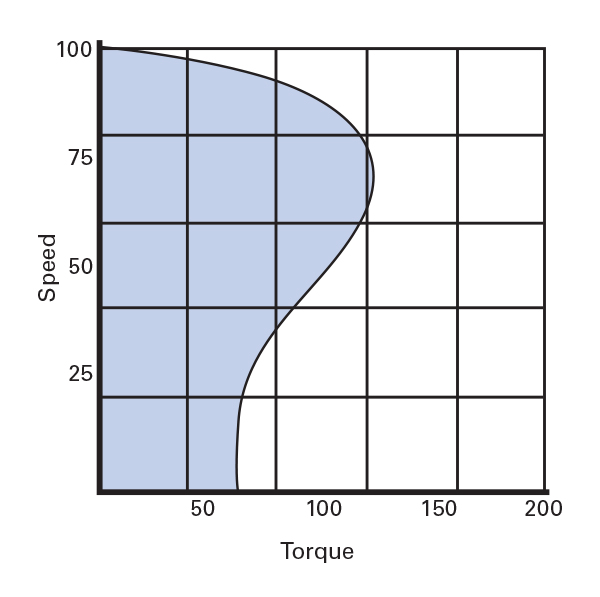
The shaded pole motor is classified as a relatively constant speed machine, and running efficiency will increase with load. Variation in applied load will not significantly affect motor speed, providing that the motor is not overloaded. See Fig. 2-19.
Normal shaded pole designs also offer the "fail-safe" feature of staring in only one direction. With split-phase and capacitor start motors, there is always the remote possibility that they may start in reverse in some failure modes (cutout switch doesn't operate, open winding, etc.).
Disadvantages: Although a shaded pole motor is rugged and inexpensive. It typically has a low starting torque and running torque. Efficiency is also low, making shaded pole motors impractical beyond fractional horsepower sizes. Shaded pole motors are generally used on light-load applications where heat can be tolerated or supplemental cooling is available. While efficiency is relatively low, for applications requiring minimal power output, this limitation is compensated for by its lower initial cost. However, with today's increased emphasis on energy savings, shaded pole operating costs cover the life of the application should be examined.
Synchronous Motors (Polyphase and Single-Phase)
The "difference" between the speed of the rotating magnetic field of an induction motor (which is always synchronous) and the speed of the rotor is known as "slip". When the rotor design enables it to "lock into step" with the field, the slip is reduced to zero and the motor is said to run at synchronous speed. Upon reaching the rated speed, fixed speed synchronous motors operate at a constant speed - the speed being dependent on the frequency of the power supply. This constant speed feature makes synchronous motors a natural drive for timing and other applications requiring a constant and predictable speed output.
Design and Operation: There are two common types of small synchronous motors, classified according to the type of rotor used:
- reluctance synchronous motors, and
- hysteresis synchronous motors.
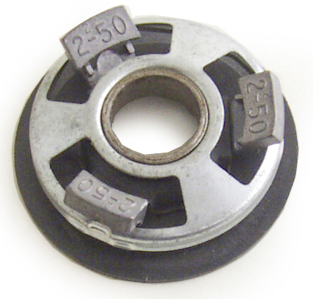
Reluctance Synchronous: A variation on the classic squirrel cage rotor, the reluctance synchronous rotor is modified to provide areas of high reluctance. This may be done by designing notches (or flats) in the rotor periphery. The number of notches will correspond to the number of poles in the stator winding. The sections of the rotor periphery between the high reluctance areas are known as salient poles. Since these poles create a low reluctance path for the stator flux, they are attracted to the poles of the stator field.
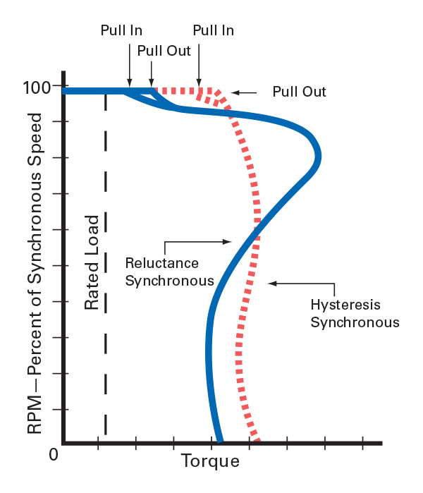
The reluctance synchronous rotor starts and accelerates like a regular squirrel cage rotor, but as it approaches the rotational speed of the field, a critical point is reached where there is an increased acceleration and the rotor "snaps" into synchronism with the stator field. If the load (particularly inertial) is too great, the motor will not attain synchronous speed. Motor "pull-in" torque is defined as the maximum load that the motor can accelerate and pull into synchronism at rated voltage and frequency. An applied load greater than the rated "pull-in" torque will prevent the motor from pulling the load into synchronism and will result in rough, nonuniform operation.
The phase relationship between the poles of the rotating field and the rotor is known as the coupling angle, expressed in mechanical degrees. This coupling angle is not rigid, but will "increase" with an increase in load. At no load, the rotor poles will line up with the field poles and the coupling angle is considered to be zero.
When a load is applied to reluctance synchronous motors, the magnetic lines of force coupling the rotor to the stator field are stretched, increasing the coupling angle. If the load is increased beyond the motor’s capability, the magnetic coupling between the rotor poles and stator field will break, and the rotor will “pull out” of synchronism. “Pull-out” torque is defined as the maximum torque the motor can deliver at synchronous speed.
Reluctance synchronous motors may be designed for polyphase operation, as well as single-phase versions in splitphase, CS and PSC configurations. These motors have characteristics comparable to their non-synchronous counterparts using the same types of stator windings. For comparable output in a given frame size, the poly-phase or PSC reluctance synchronous motor will provide quieter operation and more nearly uniform angular velocity than the split-phase or CS reluctance synchronous motor. As shown in Fig. 2-20, the reluctance rotor can be skewed to improve smoothness of operation.
Hysteresis Synchronous: Although the stator in a hysteresis synchronous design is wound much like that of the conventional squirrel cage motor, its rotor is made of a heat-treated cast permanent magnet alloy cylinder (with a nonmagnetic support) securely mounted to the shaft. The motor’s special performance characteristics are associated with its rotor design. The rotor starts on the hysteresis principle and accelerates at a fairly constant rate until it reaches the synchronous speed of the rotating field.
Instead of the permanently fixed poles found in the rotor of the reluctance synchronous design, hysteresis rotor poles are “induced” by the rotating magnetic field. During the acceleration period, the stator field will rotate at a speed faster than the rotor, and the poles which it induces in the rotor will shift around its periphery. When the rotor speed reaches that of the rotating stator field, the rotor poles will take up a fixed position.
Like the reluctance synchronous motor, the coupling angle in hysteresis motors is not rigid, and if the load is increased beyond the capacity of the motor, the poles on the periphery of the rotor core will shift. If the load is then reduced to the “pullin” capacity of the motor, the poles will take up fixed positions until the motor is again overloaded or stopped and restarted.
The hysteresis rotor will “lock-in” at any position, in contrast to the reluctance rotor which has only the “lock-in” points corresponding to the salient poles on the rotor.
Advantages: Synchronous motors operate at a constant speed fixed by the number of stator poles and the frequency of the power supply. Within the limitations of “pull-out” torque and no variation in line frequency, the speed can be considered constant.
Hysteresis synchronous motors, with their uniform acceleration characteristics, can pull into synchronism any load that is within their capacity to start and accelerate.
Application Considerations: Synchronizing characteristics of the reluctance motor require increased acceleration of the rotor at the critical point when it approaches the rotational speed of the field. For this reason, it is possible that while the reluctance motor may easily start a high inertia load, it may not be able to accelerate the load enough to pull it into synchronism. If that should happen, the reluctance motor would operate as an ordinary induction motor, but at low efficiency and very irregular angular velocity (audibly detected as a pounding noise). It is important, when applying synchronous motors, to be certain that they will accelerate the loads to synchronous speed under the most adverse load and voltage conditions. See Fig. 2-21.
In general, synchronous motors should only be applied in cases where the load needs to be driven at an exact speed. For a given output power, synchronous motors are usually larger and more costly than non-synchronous motors. In other words, for a given frame size, synchronous motors (vs. non-synchronous) have lower hp ratings and tend to be more expensive. Stated still another way, a synchronous motor will often be larger than a non-synchronous motor to drive a given application. Because of these factors, synchronous motors tend to be applied only where the synchronous feature is absolutely necessary.
To explore our AC motor, gearmotor and control products click on these links:
AC Motors AC Torque Motors AC Parallel Shaft Gearmotors AC Right Angle Gearmotors AC 3-Phase Inverter Duty Gearmotors AC Controls