What is a gearmotor?
A gearmotor consists of a small motor designed specifically with an integrated gear reducer (gearhead). The end shield on the drive end of the motor provides a dual function. The side facing the motor provides the armature/rotor bearing support and a sealing provision through which the integral rotor or armature shaft pinion passes. The other side provides multiple bearing supports for the gearing itself and a sealing and fastening provision for the gearhousing. This construction eliminates the guess work of sizing a motor and gear reducer separately.
Why use gearmotors?
Gearmotors offer advantages over separate motor and reducer combinations. The gearhead acts as a torque multiplier, allowing a small motor to generate higher torque. Integral pinions that are ground or hobbed on the armature or rotor shaft reduce noise. And shared castings result in fewer parts and “near perfect” alignment of the rotor pinion and gear train. There is a minimum risk for lubricant leakage because of “O-ring” and lip seal construction, and the compact design provides better lubrication control for various mounting configurations. Gearmotors also eliminate the need for motor/gearhead couplings, and eliminate possible bearing misalignments.
What are the features and benefits of various types of gearing?
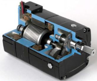
Parallel shaft: “Parallel shaft” refers to gear trains where the axis of the gear shaft is parallel to the motor shaft axis. They usually employ spur and/or helical gearing. Spur gearing is easier to manufacture and less expensive than helical gears. However, because of the greater overlapping or “load-sharing,” the transmission of power is usually smoother and quieter with helical than with spur gearing.
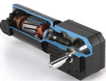
Right Angle: In right angle gear trains, the axis of the output shaft is 90 degrees to the motor shaft axis. Right angle gearmotors are used frequently in applications where space restricts the use of parallel shaft gearmotor of comparable torque. Worm gearing is the most common gear type used in this kind of gearmotor. Worm gearing can be self-locking; meaning the friction torque to the output shaft prohibits the gearbox to drive backwards. Worm gears have higher resistance to shock loads compared with spur and helical gears. In addition, the sliding tooth action of worm gears offers minimal noise. However, they are more difficult to lubricate and less efficient.
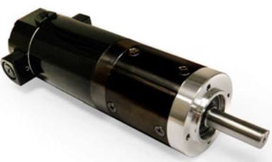
Planetary (center shaft): A Planetary gearhead is comprised of a sun gear, a ring gear, and a planet carrier assembly that uses three to five planet gears. The sun gear is generally the motor pinion, and the ring gear is the housing. The planet gears share the load, revolving around the sun gear. The output shaft typically attaches to the planet carrier of the output stage. A key benefit of planetary gearmotors is their compact size and high torque density. They provide up to twice the torque of a same-size parallel shaft gearmotor. Coaxial center shaft arrangements eliminate any output shaft offset for easier installation.
What types of motors are commonly available?
AC Induction Motors: In an AC induction motor or gearmotor, the stator winding sets up a magnetic field, which reacts with the current-carrying conductors of the rotor to produce rotational torque. The essential operating characteristics of AC induction motors and gearmotors will vary according to:
- Winding types (split-phase, capacitor run, shaded-pole, three-phase, etc.)
- Number of poles and phases, the line frequency, and the voltage of the power source
Permanent Magnet DC Motors: PMDC motors generate torque directly from DC power through internal commutation, stationary magnets and a rotating armature. They use carbon brushes that press against a commutator attached to the armature. As the armature turns, the brushes create contact with different segments of the commutator changing the current path through the winding. The rotation of the armature is a result of the interaction between the magnetic field from the armature and the stationary permanent magnet field.
Brushless DC Motors: BLDC speed-torque curves are very similar to those of PMDC motors. However, the magnets on BLDC motors rotate, and their windings are stationary. The other major construction difference is the means for switching winding phases on and off. Operation of a BLDC motor is similar to a PMDC motor except that the winding phases are switched on and off electronically by means of a control device. The control “knows” when to switch the windings because of feedback received from the rotor position Hall Effect sensors.
Copyright Bodine Electric Company © 03/2016. All rights reserved.