 Features and Benefits of PMDC Gearmotors and Motors:
- Continuous duty operation
- DC power supply (battery or speed controls – 12/24V, 90/130V, 180V)
- Reversibility at rest or during rotation with current limiting
- Relatively constant and adjustable speed
- Starting torque 175% and up of rated torque
- High starting current, relative to full load running current
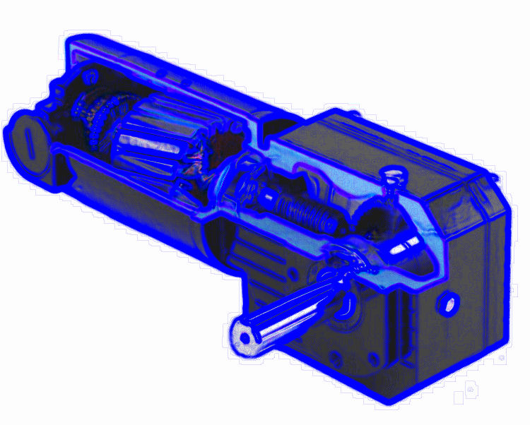
Design and Operation: Permanent magnet DC (PMDC) motors provide a comparatively simple and reliable DC drive solution in applications requiring high efficiency, high starting torque and a linear speed/torque curve. With the great strides made in ceramic and rare earth magnet materials, combined with electronic control technology, the PMDC motor is a cost-competitive solution for adjustable speed applications – delivering significant performance in a relatively compact size.
The single design feature which distinguishes the permanent magnet DC motor from other DC motors is the replacement of the wound field with permanent magnets. It eliminates the need for separate field excitation and attendant electrical losses in the field windings.
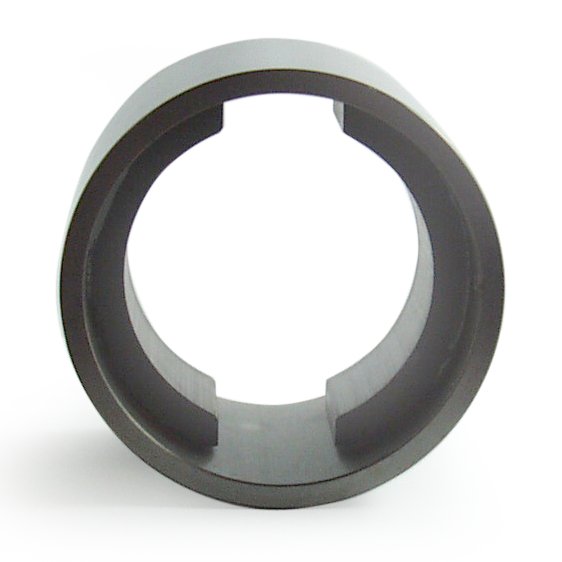 Advantages: Perhaps the most important advantage of PM field motors is their smaller overall size made possible by replacing the wound field with ceramic permanent magnets. The PM motor’s ring and magnet assembly is considerably smaller in diameter than its wound field counterpart, providing substantial savings in both size and weight. See Fig. 1. And since the PMDC motor is not susceptible to armature reaction, the field strength remains constant.
If we examine the field construction of the wound field DC motor versus the PMDC field motors, we can explain the differences in armature reaction and corresponding differences in speed/torque characteristics of the two motor types. The armature magnetizing force in a wound field construction “sees” a very high permeability (low reluctance) iron path to follow. In the PM field design, this armature magnetizing force is resisted by the low permeability (high reluctance) path of the ceramic magnet, which tends to act as a very large air gap. The net result is that the armature cannot react with the field in a PMDC motor, thereby producing a linear speed / torque characteristic throughout its entire torque range.
PMDC motors offer benefits in a number of ways:
a) They produce relatively high torques at low speeds, enabling them to be used as substitutes for gearmotors in many instances. PMDC motors operated at low speeds are especially useful where “backlash” and inherent mechanical “windup” of gearing in gearmotors can not be tolerated. It should be noted that if PMDC motors are continuously operated at high torque levels (above rated), they can generate serious overheating, or motor damage can result.
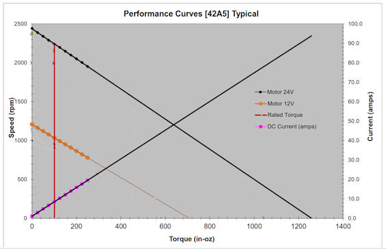 b) The linear speed / torque curve of PMDC motors, coupled with their ability to be easily controlled electronically, make them ideal for adjustable speed and servo motor applications.
c) The linear output performance characteristics of PMDC motors also make it easier to mathematically predict their dynamic performance. See PDF version.
The PMDC motor’s high starting torque capability can be a valuable asset in many “motor only” (non-gearmotor) applications as well as inertial load applications requiring high starting torque with less running torque. PMDC motors function well as torque motors for actuator drives and in other intermittent duty applications.
The size reduction in PMDC motors is generally accomplished without any significant change in the temperature rise rating for a given horsepower. In fact, the electrical efficiency of the PMDC motor is very often 10% to 15% higher due to the elimination of field copper losses which occur in wound field motors. PMDC motors can be produced in TENV (totally enclosed non-ventilated) construction, eliminating the need for fans and providing much greater application flexibility.
With their higher inherent efficiency, PMDC motors and gearmotors offer lower current drain for more efficient battery operation in portable applications. The permanent magnets also provide some self-braking (less shaft coast) when the power supply is removed. PMDC motors require only two leads (shunt-wound motors require four). The leads can be reversed by simply changing the polarity of the line connection. Dynamic braking is achieved by merely shunting the two leads after disconnecting them from the power source. Permanent magnet DC motors also provide similar performance characteristics to shunt-wound DC motors when used with all common control methods (except field weakening).
Design Considerations: While today’s ceramic magnets have properties which make them very reliable, certain characteristics of these materials must be thoroughly understood if proper operation of ceramic magnet PMDC motors or gearmotors is to be obtained. At lower temperatures (0°C and below), ceramic magnets become increasingly susceptible to permanent demagnetizing forces.
Strong armature fields capable of producing permanent demagnetization of the magnets take on greater importance at lower temperatures. Therefore, special attention must be given to overload current conditions including “starting,” “locked rotor” and “plug reversing” when applying PMDC motors to low temperature use. Plug reversing requires current limiting, even at normal temperatures.
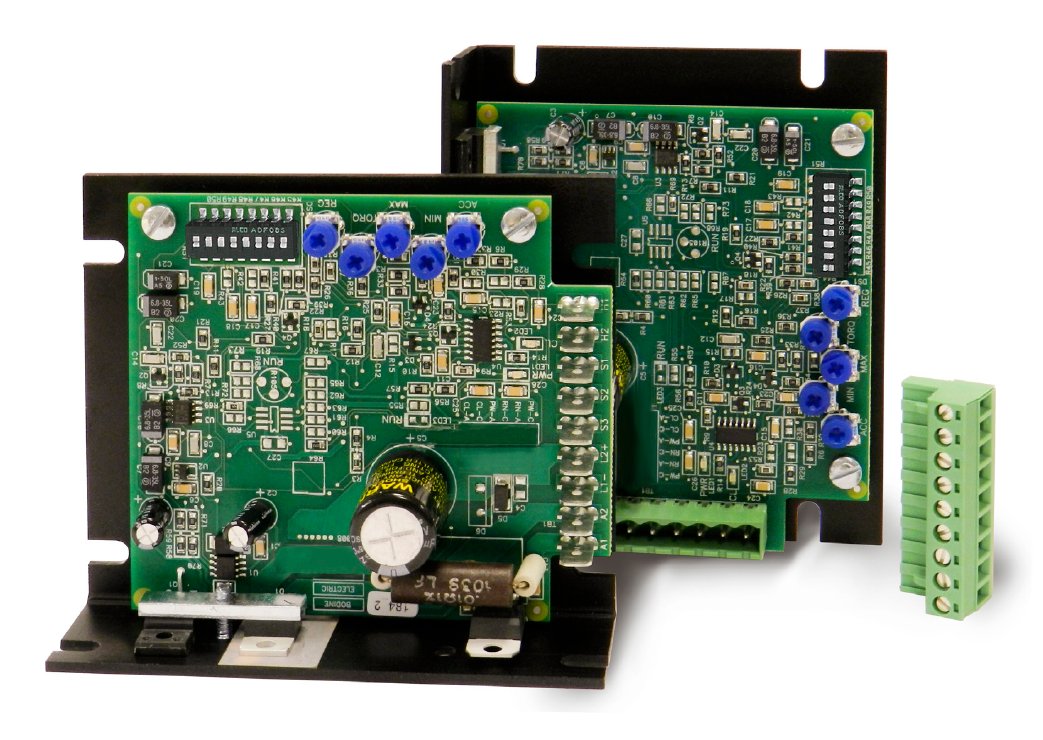
Bodine 12 and 24 VDC Speed Controls for PMDC Motors and Gearmotors
The design of the motor’s power supply is also important. PWM and SCR controls are designed to provide current regulating and / or limiting features to protect the motor or gearmotor. The actual application parameters involved vary with each particular PMDC motor design, since the protection against demagnetization is part of the motor’s design and must be considered accordingly. It is best to consult the manufacturer if low temperature use or plug reversing is contemplated.
As operating temperature increases, the residual or working flux of PMDC motors decreases at a moderate rate. This flux decrease is much like the decrease of field flux strength in wound field motors as copper resistance increases with temperature.
Application information: Because of their high starting torque characteristic, care must be exercised in applying PMDC gearmotors. A PMDC gearmotor application should be carefully reviewed for any high inertial loads or high starting torque loads. These types of loads could cause the motor to transmit excessive torque to the gearhead and produce output torque which exceeds its design (rated) limits. PWM or SCR speed controls with built-in current limiting circuits, or overload slip clutches are sometimes employed to protect gearing used with PMDC motors.
This blog post is from an updated section of Bodine Electric’s Small Motors Handbook. To download this article as a PDF, or to download the entire Handbook or sections of it, please click here. Or go to: http://www.bodine-electric.com/handbook.
For a complete look at our stock and custom PMDC gearmotors, motors, and controls, click here: http://www.bodine-electric.com/dcmotorsolutions.
Copyright Bodine Electric Company © 01/2013. All rights reserved.