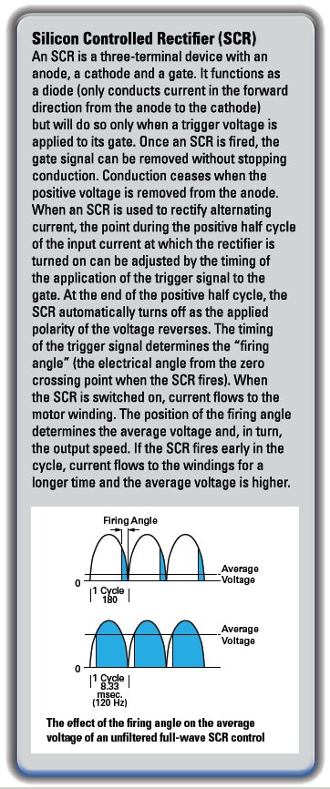
Basic DC motor speed controls accomplish the conversion of AC power to DC with varying degrees of DC voltage “purity.” For proper control selection you’ll need to identify which performance criteria are important to your application. We’ll review how different speed controls affect the quality of DC output and consequently, the performance of your DC gearmotor or motor. In addition, we’ll discuss how to evaluate whether filtered or unfiltered DC motor speed controls are best for your permanent magnet DC (PMDC) motor application.
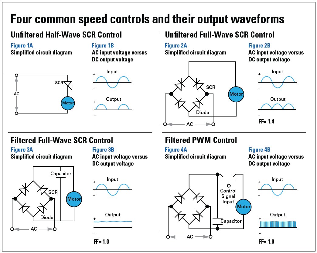
To better understand DC output characteristics, and how they affect motor performance, we’ll compare the output waveforms of four common speed controls.
1. The unfiltered half-wave Silicon Controlled Rectifier (SCR) control is the most basic speed control available. Very simply, it places a single SCR in series with the DC motor’s armature winding as shown in Figure 1A (see page 2). This converts the AC into DC by simply blocking the negative half cycle of the AC sine wave. As can be seen in Figure 1B, this produces a fairly choppy output for the motor and only faintly resembles a true DC current.
2. The unfiltered full-wave SCR control improves on the unfiltered half-wave SCR control by adding another SCR and two diodes to form a bridge rectifier as shown in Figure 2A. Instead of just blocking out the negative half cycle of the AC sine wave, the unfiltered full-wave SCR control inverts it into another positive half cycle. As can be seen in Figure 2B, this output still looks choppy, but it’s getting closer to looking like a smooth DC current.
3. The filtered full-wave SCR control design utilizes a large filter capacitor that is placed across the output of the control as shown in Figure 3A. Since a capacitor stores energy during the rising portion of the AC sine wave and then discharges it slowly during the falling portion, it effectively smoothes out the choppy output current created by the switching of the SCRs. As a result, a smooth output current is produced that approximates pure DC, as shown in Figure 3B.
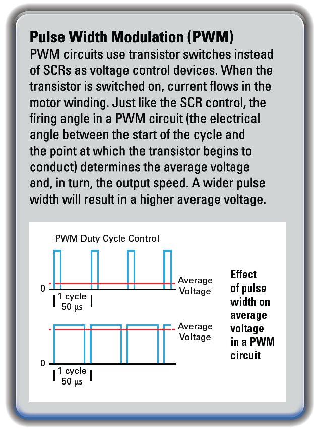
4. A filtered Pulse Width Modulation (PWM) control uses a different method to produce a smooth output current that is comparable to that of a filtered full-wave SCR control. The AC supply is first rectified and filtered before it is switched on and off to vary the output voltage, as shown in Figure 4A. In contrast, the filtered full-wave SCR control simultaneously rectifies and switches the AC supply, then filters it after switching. The output current shown in Figure 4B may look choppy, but due to the rapid switching of the PWM controls and the high inductance of typical DC motors, the current appears to be pure DC
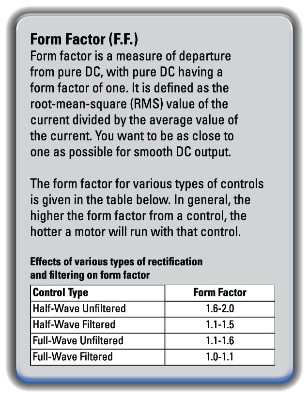
Filtered versus unfiltered speed controls: As we can see, subtle differences in control design affect the purity, or form factor (FF), of the DC output power and can result in significantperformance changes in motor and control operation. Motor speed range, continuous torque rating, motor operating temperature, brush life, AC current draw and electromagnetic interference (EMI) are among the items that can be adversely affected and can have severe consequences if not taken into account in the system selection process.
Motor temperature. Operating a motor with a higher form factor, unfiltered control can result in motor winding temperatures as much as 30°C higher compared to operation with a filtered control. From page 8-23 of the Small Motor, Gearmotor and Control Handbook from Bodine (the Handbook): “The form factor is an important consideration with motors designed to operate on direct current. When operated from rectified power versus pure DC, the increase in motor heating for a constant output is approximately proportional to the square of the form factor. For example, a motor operating from half-wave rectified DC current will have approximately 2.5 times the heat rise of the same motor operating on 1.0 form factor DC.”
This is especially important in applications where the motor is located at a place in the machine where people can touch it. Certain safety standards dictate that any parts exposed to human touch can’t exceed a surface temperature of 60°C. A hot motor might also negatively impact other components around it by raising the surrounding ambient air temperature. This effect will be even greater if the motor is located in a sealed enclosure with other temperature-sensitive hardware.
Motor life. Besides the safety concerns previously mentioned related to higher motor operating temperature, a hotter motor will also have a shorter life expectancy.
From page 7-34 of Bodine’s Handbook: “Motor life expectancy is a function of total temperature. Insulation, lubricant and seals are all affected by temperature. This is illustrated by the following:
1) As a general rule, ball bearing or gear lubricant life is halved for every 25°F (approximately 14°C) increase in temperature. Heat will eventually degrade most lubricants and seals, leading to leakage, increased friction and extra maintenance.
2) Generally, the motor insulating life is halved for each 10°C increase in total temperature.”
Long life is especially important for motors used in industrial machinery that might be operated during three working shifts a day, or 24 hours per day. Motors are generally designed for a certain number of operating hours, so a motor designed for 10,000 hours of running time would be expected to last almost five years if used eight hours per day and five days per week. But that same motor might last just over one year if used 24 hours per day and seven days per week. If that life is further cut in half because of the extra heating from an unfiltered control, then that motor might have to be replaced every six months.
Brush life. With an unfiltered control a high peak current is necessary to maintain the necessary average current output for a given power requirement. These higher peak currents contribute to accelerated brush and commutator wear, reducing brush life to as much as 50% compared to operation with a filtered control. This is even more evident in critical high speed applications like laboratory centrifuges. In these instances, brush life is short to begin with because of the increased linear speed between the brushes and the commutator when operating at speeds as high as 15,000 RPM. Using an unfiltered control in these situations means you might have to replace the brushes every few months depending on how often and how long the centrifuge is used.
Speed range. Maximum speed can be 45 percent higher with filtered controls. The maximum output voltage of an unfiltered control powered from a 115 VAC line is 90 VDC, whereas the maximum output from a filtered control is 130 VDC. Since the speed of a DC motor is proportional to the DC voltage, the motor will run faster with a filtered control (typically 2,500 RPM) than it will with an unfiltered control (typically 1,725 RPM).
A wide speed range is important in applications that require operation at both a very low speed and a very high speed. For example, in a printing press, motors are used to drive the pumps that supply ink. During the printing process, the motors run at a low speed and maintain a constant pressure. At the end of the printing process, there is a flushing process to clean the ink out of the system. During the flushing process, the motors run at a high speed.
Continuous torque. A motor might develop as much as fifty percent greater continuous torque with a filtered control. Motor torque ratings are based on thermal limits of the motor insulation system, among other things. For example, consider a certain motor with Class A insulation that is rated for a continuous load of 101 oz-in. with a 1.0 FF control in 40°C ambient conditions. The National Electrical Manufacturers Association (NEMA) standards dictate that the temperature rise of this motor under rated load not exceed 70°C. If this same motor were used with a 1.6 FF control, the load would have to be reduced to 58 oz-inches, or only 57 percent of the 1.0 FF rating, to keep the same temperature rise of 70°C.
AC Current draw. AC root-mean-square (RMS) current draw of unfiltered SCR control can be 20 percent lower. During each half cycle of the AC line voltage, a large current spike occurs in a filtered SCR control because of the charging of the filter capacitor. Depending on the control and size of the motor used, this current spike could be five times the actual DC current going to the motor. This raises the RMS AC current going into the control and puts a greater demand on the AC power supply and other components like circuit breakers, relay contacts, switches, fuses, etc. In a large factory where hundreds of machines in the same operation are powered at once, the cost of the additional AC power required to drive the filtered control might outweigh other cost considerations.
EMI. Unfiltered controls can produce less electromagnetic interference (EMI). The same current spikes described above might cause problems in applications that have other components sensitive to EMI or in applications that are required to meet a certain Electromagnetic Compatibility (EMC) or Federal Communications Commission noise limit. Even though both types of controls would require AC line filters to meet European EMC standards, the filtered control might need a more expensive one because of the higher current rating.
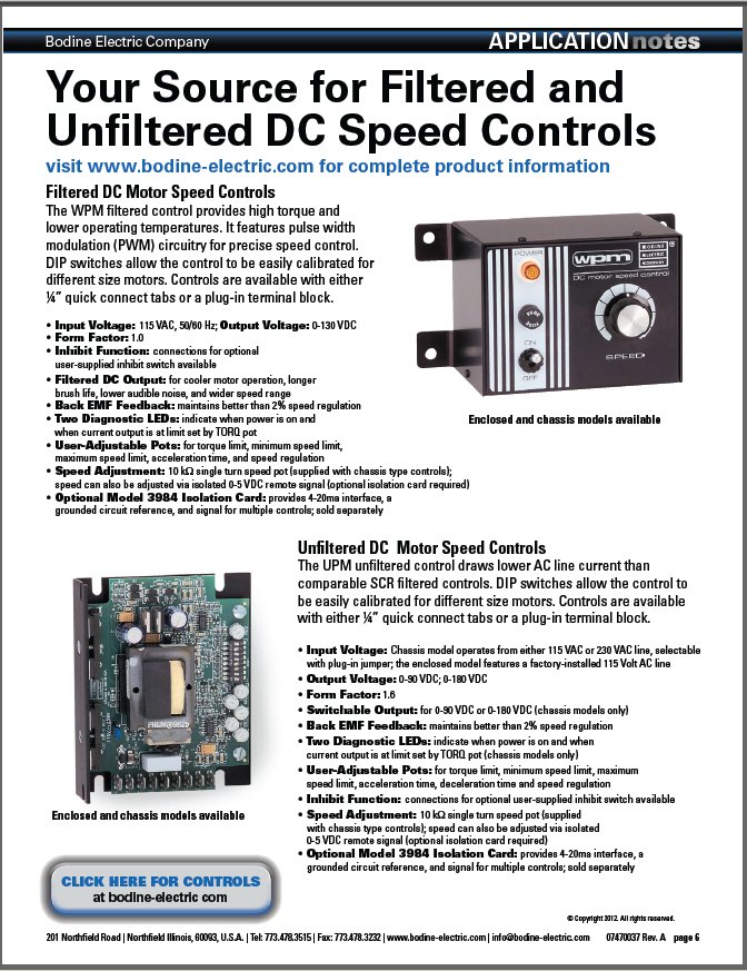 SUMMARY. Proper speed control selection depends on an understanding of how DC motors are affected by various grades of DC voltage. The degree to which alternating current is rectified (converted) to direct current will determine the overall efficiency of the motor and control system. We measure the departure from pure DC using the term form factor, with pure DC having a form factor of 1.0. When motors are operated from rectified power versus pure DC, the increase in motor heating for a constant output is approximately proportional to the square of the form factor. For continuous duty applications, this increased heating effect must be accommodated. If you’re using a cheaper unfiltered control, you might need to purchase a larger, more costly motor to keep motor operating temperatures within design limits. If you select a filtered control, which lowers motor operating temperatures, you might save on overall system cost since a smaller, less expensive motor is all that’s necessary. Smaller motors offer the additional benefits of lower weight and space savings.
Before selecting a DC motor speed control for your application, determine the performance criteria important to your operation and then evaluate whether a filtered or unfiltered speed control will be better for your brush type PMDC motor application.
To download this Application Note as a PDF, please click here. To review our selection of DC motor speed controls, click here.
Edited By Eman Elashye: Eman Elashye is an Application Support Specialist at Bodine Electric Company. She has a degree in Electrical Engineering and she works in our customer support group in the Chicago area.
Copyright Bodine Electric Company © 10/2012. All rights reserved.
