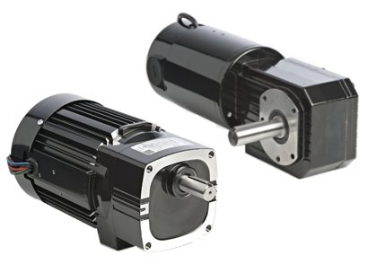
To select the best gearmotor for an application, one must go into more detail than just selecting the best suitable output speed and torque. Here are five criteria you should consider.
1. Gearmotor Mounting Orientation
Gearmotors are typically designed to be mounted with the gearbox level with the motor, and with the drive shaft in horizontal orientation. Other mounting positions are possible, depending on the type of gearmotor and how its gearbox is lubricated. If you require non-standard mounting (e.g. vertical), the first step in choosing a gearmotor should be to call the manufacturer’s technical support team.
Most fractional horsepower (FHP) gearmotors feature unvented gearheads that are lubricated for life, but some gearmotor types are oil lubricated and others are grease lubricated. If an oil lubricated gearmotor is mounted in a position other than horizontal, the chance of leakage increases in both static and dynamic conditions as the shaft seals wear. Grease lubricated products are less prone to leakage, but gear life can be compromised.
Design Tip 1: Oil vs. Grease
Oil provides more consistent lubrication to the gear teeth under load conditions. Grease provides greater flexibility in mounting and minimizes the risk of leakage. Despite advantages, oil is not always used in smaller fractional HP gearmotors because of these sealing considerations. If a non‑standard mounting orientation is required, one possible alternative is a semi-fluid grease. Avoid mounting an oil-filled gearbox directly above the motor. There is a shaft seal between the gearbox and the motor, but seals don’t last forever. Eventually the lubricant will find a path into the motor. This could interfere with commutation in a permanent magnet DC motor, the centrifugal starting switch in an AC split‑phase motor, or the electronic commutator assembly in a brushless DC motor. If the drive shaft must point upward, then a grease-lubricated, right angle gearmotor would be a better solution. If you require a non-standard mounting position, you may need to consider a custom gearmotor with modified lubrication or fill level.
2. Gearhead Efficiency
The worm gears found in most right angle gearboxes are less efficient and generate more heat than the spur or helical gear assemblies used in parallel shaft gearboxes. Therefore, right angle gearmotors often require a larger motor to match the output torque of a parallel shaft gearmotor with the same gear ratio. The efficiency of the worm gears is even worse at low speeds, providing less torque for starting and acceleration.
3. Self-Locking Right Angle Gearheads
“Self locking” right angle gearboxes can’t be driven backwards by applying constant torque to the output shaft. These gearboxes can provide holding torque even when the power to the gearmotor is turned off. This is desirable in applications where a load is expected to remain stationery even after the power to the gearmotor is turned off. However, this is not recommended as a “fail-safe” application solution because holding torque diminishes as the gears become worn or if shaft vibration occurs.
Design Tip 2: When to Use Brakes
In applications where a load has to be held securely during a power-off condition, an external holding brake should be added to the motor or gearmotor. The brake is typically installed on the high-speed or accessory shaft (armature or rotor shaft) and not on the drive shaft (output shaft).
4. Noise and Load
Gearboxes are designed to be quiet, but some are quieter than others. In some cases metallic gears produce more noise than non-metallic gears, and helical gears tend to be quieter than spur gears. The noise from a gearbox is affected by the number of gear stages, the load, and armature/rotor input speed. Some smaller parallel shaft and planetary gearboxes use a Nylon-type first stage gear as a way to reduce noise and vibration. Worm gears are generally quieter than spur/helical gear reducers because they operate on a sliding action. Because the worm and gear teeth are under crushing rather than cantilever loads and more teeth are usually in contact, worm gears have higher resistance to shock loads than spur or helical gearing.
5. Gearmotor Life
Gearmotor life is affected by many factors. The obvious ones are operating speed, load, duty cycle, and ambient temperature. The higher any of these operating conditions are, the sooner the gearhead components will wear out. But there are also design details inside a gearbox that determine the gearmotor’s life. For example: the sliding action of worm gears is more difficult to lubricate and is less efficient than the rolling action of spur and helical gearing. Therefore, metallic worm and gear teeth will wear faster than metallic spur and helical gear teeth. Non-metallic gears will wear slower than metallic gears if no severe or shock loads are applied. Oil lubricated gears will last longer than grease lubricated gears because oil provides more consistent lubrication to the gear teeth under load conditions.
Another design detail that can affect gearmotor life are the motor shaft and output shaft ball bearings. Possible causes of premature bearing failure can be foreign materials from dirty grease or ineffective seals, grease deterioration due to excessive temperature or external contamination, or electrical arcing due to shaft currents.
Design Tip 3: Signs of Bearing Wear
Some early warning signs for bearing problems can be an increase in temperature differential between the motor and the bearings, an increase in bearing noise, or an increase in torque (load) of the motor, resulting in an increased current draw by the motor/gearmotor.
To download the PDF version, click here.
Copyright Bodine Electric Company © 08/2012. All rights reserved.

