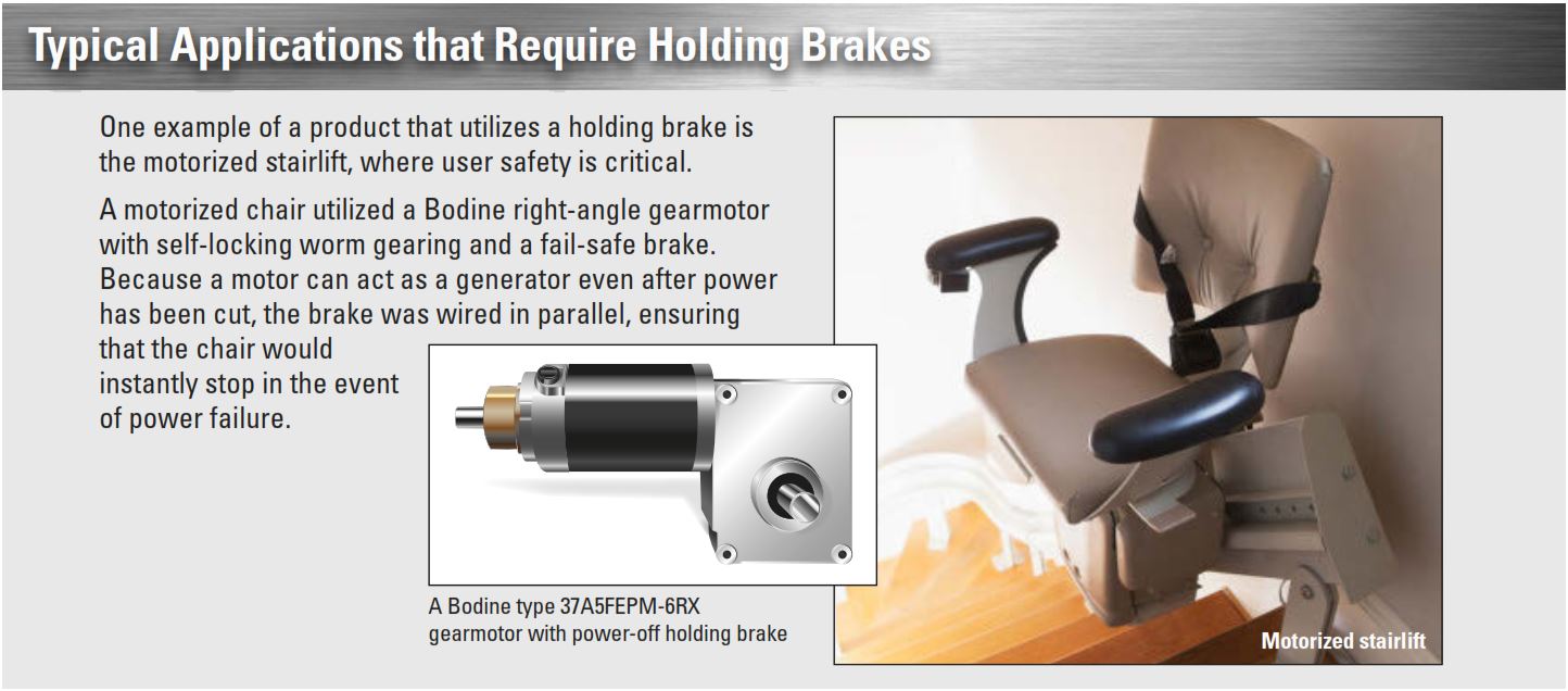
Holding, or “Power-Off,” brakes provide extra safety in applications where the load must remain in position in the event of power loss or equipment failure. Our design engineers have helped OEMs develop brake systems for hundreds of AC and DC applications, from home stairlifts to industrial applications. In this article, we focus on the principles of operation for the most common type of electromagnetic brake, the power-off design. For more information on clutches and braking techniques, see Chapter 10 in the Bodine Handbook.
Principles of Operation and Terms 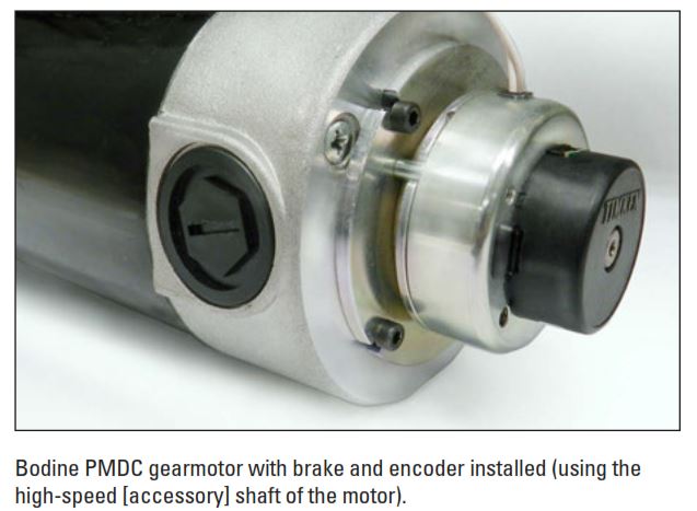
The friction disc of a power-off brake is constrained and does not allow rotational motion when no voltage is applied to it. Another common term for this design is a “fail safe” brake.
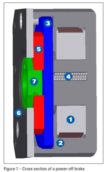
The brake is designed with a wound coil that resides within a steel cup body. When voltage is applied, the armature plate is pulled toward the cup body by the magnetic force. The force is high enough to overcome the compression springs. When no voltage is applied, the compression springs exert a force on the armature plate to hold the friction disc firmly against the pressure plate, prohibiting rotation. The friction disc is coupled to the hub by a close fit geometric shape, usually hexagon or spline.
Brakes can be designed for any DC voltage. For AC voltage brakes, a bridge rectifier is used to convert AC voltage into DC. The bridge rectifier is either internal or external to the brake depending on the size of the brake.

Dynamic vs. Static Braking
Depending on the type of application, either a static or dynamic brake may be required. The power-off brake design uses a friction disc material specific to static or dynamic braking applications. The more common version is the static brake design, where ideally the brake is engaged after the motor shaft has come to a stop. Static brakes are intended to hold static loads and the friction material experiences negligible wear over its life. Dynamic brakes are designed with a more durable friction material that wears over the life of the brake. When compared in a similar mechanical size package, dynamic brakes frequently will have a lower published torque rating than static brakes.
Brake Performance

Typical power-off holding brake
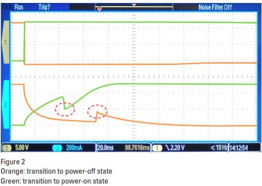
The brake has two states: power off and power on. During the transition to the power-off state, the magnetic field decays because of the removal of voltage to the brake. Here, the armature loses its magnetic couple with the wound coil, which clamps the friction disc to the pressure plate, applying the holding torque. The manufacturer can adjust the transition time, but is typically in the millisecond range. The performance of a 15in-lb. brake is shown in Figure 2. The sharp “spike” during the voltage decay is where the armature engages with the friction disc. Actual transition time is 60 milliseconds.
While charging the coil, there is a sharp “spike” when the armature makes complete contact with the wound coil and releases the friction disc. Actual time for this event is 32 milliseconds.
 Brakes are designed to operate continuously without overheating in the static holding position. Designs that include both dynamic and static braking require brakes with intermittent ratings. The duty cycle (braking and stop cycle) determines this rating.
To download a PDF version of this blog post, please click here.
Copyright Bodine Electric Company © 06/2015. All rights reserved.