Load Testing a Drive Application with a Brushless DC Gearmotor and Control By Eman Elashye
 When designing a new piece of equipment that uses motors or gearmotors, design engineers must calculate how much motor torque will be needed to drive their application load. If the gearmotor or motor is undersized and too small, the product will be underpowered and likely not meet all application requirements. If the gearmotor or motor delivers more power and torque than required, then it adds unnecessary cost, requires more space and can negatively affect the total weight of the equipment.
This tech note provides the design engineer with a procedure on how to check his or her calculations against real-world performance by load testing the application. A good way to determine how much the actual load is on a motor or gearmotor is to measure the amount of current it draws. Three-phase brushless DC (ECM) motors present a challenge to the engineer who wants to measure motor current. If the current is measured through the motor leads (i.e. the motor phases), the resulting current values will be useless and essentially make no sense.
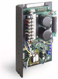
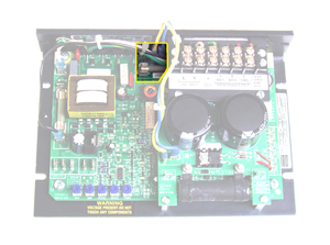
There is a simple way to accurately measure the current through the motor: measure the current through the motor fuse on the brushless DC control.* The current measurement provides the DC bus current before it goes into the 3 phases of the motor, and therefore can be used to calculate the load (torque) at the motor/gearmotor shaft. This is possible because just as in PMDC motors or gearmotors, the measured current is directly proportional to the load (required torque). The measured DC bus current should be very close, if not equivalent, to the nameplate rated current, if the motor or gearmotor is loaded to the nameplate rated torque. Once the current measurement is obtained, the motor torque is calculated by multiplying the torque constant (Kt) for the motor/gearmotor by the current value measured. Gearmotor output torque can be calculated once the motor torque has been determined.
Kt (oz-in./A) x I(A)=T (oz-in.)
Test Procedure:
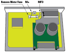
1. Remove the motor fuse from the on-board fuse holder.
2. Connect floating wires to M+ and MF3.
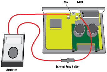
3. Place the motor fuse into an external fuse holder.
4. Connect the fuse holder and the ammeter in series with M+ and MF3 as shown in figure 3.
5. Measure the DC current using an ammeter.
* This test will only work with a non-PWM control, such as Bodine type ABL-3911 and ABL-3921. It will not work with a PWM control, such as Bodine’s low voltage models ABL-3905 or ABL-3907.
Eman Elashye is an Application Support Specialist at Bodine Electric Company. She has a degree in Electrical Engineering and works in their customer support group in the Chicago area.
You can download the PDF version here: Bodine Application Notes
p.s.: This method also works with our filtered PMDC motor speed controls (type WPM or FPM) and permanent magnet DC (PMDC) gearmotors and motors.


