Application Notes & Gearmotor Tips:
When a permanent magnet DC (PMDC) motor fails to operate properly, or fails to run at all, one sensible troubleshooting step is to measure the winding resistance to determine if there’s an open circuit or a short circuit, either between turns of the same winding, between two windings in the same motor, or between a winding and ground. This is a fairly simple procedure using an ohmmeter on an AC motor or a brushless DC motor, but it is not so simple with a brush type (PM) DC motor or gearmotor.
Since an ohmmeter can’t be used to directly measure the armature circuit resistance in a PMDC motor or gearmotor, the resistance has to be calculated.
If you have tried to measure armature circuit resistance with an ohmmeter (via the motor leads), you have found that the result is an unusually high reading. You might have thought that the armature was in a position where the brushes were bridging two commutator bars on each side. But turning the armature provided no better resistance reading. This is because armature circuit resistance cannot be measured accurately with an ohmmeter.
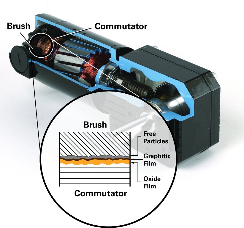
Because the connection between the brushes and the commutator is not a solid one, the gap between the two components represents additional resistance to the low voltage and low current of a typical ohmmeter power source. The additional resistance comes from the oxide film formed on the surface of the commutator and the free particles in the gap, as shown in the image below (the graphitic film is conductive). The same oxide film and free particles don’t represent a significant resistance to the higher voltage and higher current of a typical DC motor power supply. Since an ohmmeter can’t be used to directly measure the armature circuit resistance, the resistance has to be calculated.
Test Procedure:
1. Before the armature circuit resistance can be calculated, the motor must be set up in a way such that both the armature and the motor frame are not permitted to turn. In the case of a gearmotor with a fairly high gear ratio, this could require a rather sturdy restraint. However, the stall torque of a DC motor is proportional to the applied voltage, so reduce the voltage until you are able to hold the gearmotor in place with the armature locked.
2. Make sure that the voltage is still high enough to drive a current of at least 10% of the motor’s nameplate rating or 0.25 Amp, whichever is higher.
3. Starting with a “cool” motor (meaning the winding temperature is the same as the ambient, which should be at a normal room temperature of
+25° C [+77°F]), measure the applied voltage and the current draw at least five times, with the armature in a different angular position each time.
4. Do each test quickly to keep the motor from heating up, because winding resistance changes with temperature and these changes would affect the accuracy of the tests.
The armature circuit resistance can then be calculated by using the following basic steady state DC motor equation:
E = I x R + (Ke x w), where
E = applied voltage
I = current
R = armature circuit resistance
Ke = voltage constant
w = speed (omega)
Since speed = 0 with the armature locked in place, the back emf voltage (Ke x w) = 0 and the equation can be simplified to:
E = I x R
This can be rewritten to solve for the armature circuit resistance:
R = E/I
Use this equation with the current and voltage measurements from each of the five tests and then average the results for the resistance. Even if you never use this method yourself, you can now explain to your customers why they have not been able to measure the correct armature circuit resistance with an ohmmeter and then suggest this more reliable method.
You can download the PDF version of this application note by clicking on this link.
Examples:
1. Bodine Model 6422 (24 VDC, type 33A7)
B+K Precision multimeter reading: 0.674 Ω
This test method: 0.196 Ω
1. Bodine Model 6035 (130 VDC, type 33A5)
B+K Precision multimeter reading: 11.41 Ω
This test method: 11.13 Ω
Note: The bar-to-bar resistance measured directly between two opposing commutator bars does not provide the “full picture”. The armature circuit resistance provides the sum of resistances in the PMDC motor — from the commutator to the external motor cord and everything in-between (brushes, brush holders, springs, winding, terminals, etc.)
Copyright Bodine Electric Company © 04/2012. All rights reserved.


