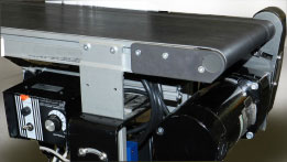
This post provides step-by-step instructions for how to size and select a gearmotor in a belt-driven conveyor application. Before sizing a gearmotor, we must first know the application requirements.
For our example, the conveyor system requirements are as follows:

- Able to handle a 200lb (90kg) load
- Have adjustable speed, up to 12 inches/second
- Be able to accelerate in 1 second
- Powered by 115VAC
- Has 4 inch (102mm) diameter rollers
- Allows for frequent starts/stops
- Zero gearmotor maintenance
Now we must translate these requirements into gearmotor specifications. First, we will determine the required speed and torque, then we review the gearmotor options that best fit with our conveyor specifications, and last, we select a stock gearmotor and drive.
Step 1: Determine speed and torque
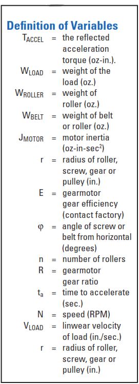
In order to size a gearmotor, we need to identify:
- Speed (N) – The speed required to drive the application per its specifications
- TACCEL – The reflected acceleration torque
- TFRICTION – The reflected friction torque
- TBREAKAWAY – The reflected breakaway torque
- TGRAVITY – The reflected gravity torque
- TCONT and HPCONT – The continuous torque and horsepower needed for the application
Note: TACCEL may be ignored unless acceleration time is critical. TACCEL and TGRAVITY can be calculated using the equations in this paper. TFRICTION and TBREAKAWAY will have to be measured using one of the methods described in this paper. TBREAKAWAY is only a factor during starting. TFRICTION and TGRAVITY will be used to determine continuous torque (TCONT). TGRAVITY is only considered when the belt is not mounted horizontally.
Step 1: Determine speed and torque, contd…
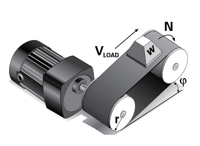
A. Speed
Equation 1: N = (9.55 • VLoad ) / r
Where 9.55 has the units sec-rev/min. From the given system requirements, we know VLoad = 12 in/sec and r = 2 in, therefore N = 57.3RPM.
B. TACCEL
TACCEL may be ignored unless acceleration time is critical. It will be used in determining if the selected gearmotor has adequate starting capability.

Equation 2:
We know that WLOAD = 200 lbs. x 16 oz/lb. = 3,200 oz., VLOAD = 12 in/sec., ta= 1 sec., r = 2 in. and we will assume that
JMOTOR = WROLLER = WBELT = 0 for our initial calculation. Therefore, TACCEL = 199 oz-in.
C. TFRICTION
The friction torque (TFRICTION) can be estimated through measurements as described in the “Test Motor Method” on page 4 of the PDF or at the end of this blog post. For our example, we will assume the measured TFRICTION = 100 oz-in.
D. TBREAKAWAY
The reflected breakaway torque can be estimated through measurements as described in the “Spring and Pulley Method”, the “Torque Wrench Method”, or the “Test Motor Method” on page 4 of the PDF or at the end of this blog post.
For our example, we will assume the measured TBREAKAWAY = 120 oz-in.
E. TGRAVITY
Gravity torque only needs to be considered when the belt is not mounted horizontally. It is a positive number when the load is moved upward, and a negative number when the load is moved downward.
Equation 3: TGRAVITY (oz-in.) = r WLOAD sin φ
In our example, the conveyor is not inclined, therefore φ= 0°, which means that TGRAVITY = 0.
F. TCONT and HPCONT
Now we can calculated the continuous torque required for the application. This will be the torque value we will use to determine the continuous horsepower required, and these are the values, along with the calculated speed, that we will use to select a gearmotor.
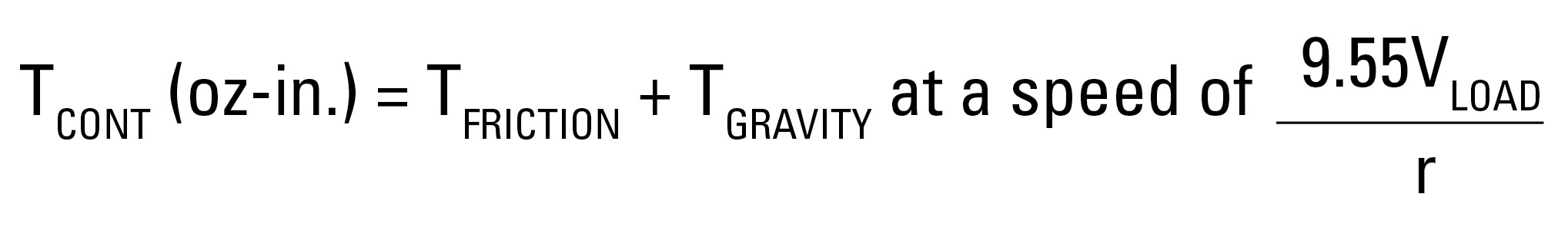
Equation 4:
Therefore, TCONT = 100 oz-in = 6.25 lb-in.
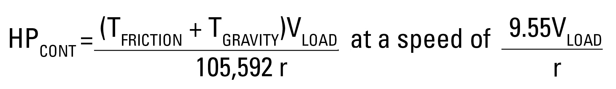
Equation 5:
Therefore, HPCONT = .00568 = 1/176.
We have completed all of the initial calculations required to select a gearmotor. Once we have one selected, we must ensure that its starting torque capability is greater than or equal to the sum of all 4 torques above (TACCEL, TFRICTION, TBREAKAWAY, and TGRAVITY).
Step 2: Determine the type of motor/gearmotor that is best for the application.
We can determine what type of motor to use by answering some basic questions:
Is the available power supply AC or DC? AC
If AC, is the power supply 1 phase? YES
If AC, is the power supply 3 phase? NO
If DC, is the power supply low voltage (12/24VDC)? NO
If DC, is the power supply high voltage (90/130VDC)? NO
Does the application require adjustable output speed? YES
Does application require point-to-point positioning? NO
Does application require controlled acceleration and deceleration, even when an overhauling load is present? NO
Would a brush motor be undesirable because of airborne dust, mechanical noise, electrical noise or brush maintenance needs? YES
Based on the above answers a Brushless DC Motor/Gearmotor with AC-Powered Speed Control or a 3-Phase AC Motor/Gearmotor with AC-Powered Speed Control would be the best choice for this application.
Step 3: Select a Gearmotor
Right Angle Gearmotor vs. Parallel Gearmotor
- Does the application have sizing/spacing constraints? (sometimes, right angle is better)
- Does the application require a self-locking gearmotor to prevent backdriving? (choose right angle, high ratio)
- Is gearmotor efficiency important for the application? (choose parallel shaft, more efficient)
In this case, none of the reasons for choosing a right-angle (worm) gearmotor are present, so we will choose a parallel shaft gearmotor.
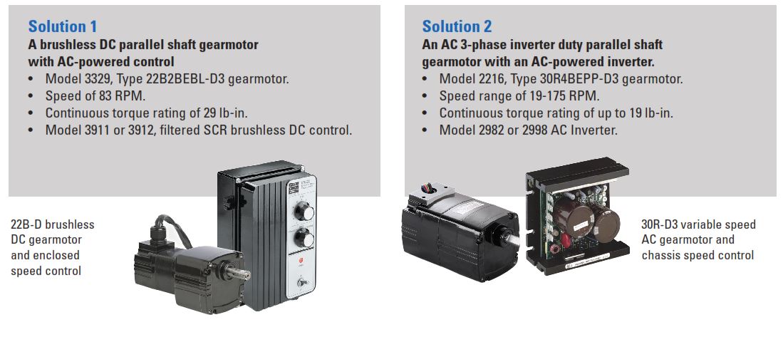
Step 4: Select a Stock Product
The following Bodine products match the specifications determined above, and the types of gearmotors we decided to use for this application.
Methods for Measuring the Breakaway and Friction Torque of a Machine. Excerpt from the Bodine Handbook, Chapter 7, and the Bodine Selection Guide (PDF).
The String and Pulley Method
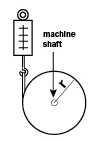
Affix a pulley to the shaft of the machine to be driven (see Figure A). Secure one end of a cord to the outer surface of the pulley and wrap the cord around it. Tie the other end of the cord to a spring scale. Pull on the scale until the shaft turns. The force, in pounds indicated on the scale, multiplied by the radius of the pulley (in inches) gives the breakaway torque in pound-inches.
Torque Wrench Method
A simple torque wrench can be applied to the shaft of the machine to be driven. Turn the wrench as you would an ordinary pipe wrench, and when the shaft begins to rotate, read the value for TBREAKAWAY (in ounce-inches or pound-inches) on the torque wrench gauge.
Test Motor Method
Both AC and DC test motors or gearmotors can be used to measure breakaway torque, (TBREAKAWAY), and friction torque, (TFRICTION). This method requires more time and instrumentation, but can be well worth the expense in the long run. It is the best way to optimally match machine and drive unit, and is popularly used for all high volume OEM (original equipment manufacturer) applications. After using these methods, contact the motor manufacturers’ sales engineer for help in interpreting the data.
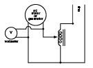
Test With An AC Drive – Use a torque wrench or “string and pulley” to find the approximate size of the test motor or gearmotor needed. An AC motor or gearmotor whose rated output speed is close to the desired “final” speed of the machine should be obtained. Next, hook up the AC drive, along with a variable autotransformer to the load (See Figure B). With a voltmeter connected to the line, increase the voltage supplied by the autotransformer until it starts and accelerates the load up to speed (to check speed use a tachometer or stroboscope). Record the starting voltage at all possible starting locations of the device. This is proportional to the TBREAKAWAY. Next, back off slowly until the motor stalls. Read the voltage. This is proportional to the TFRICTION.
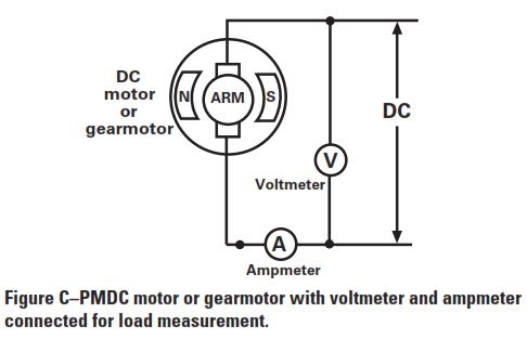
“Test” With A DC Drive – The DC method requires that both voltage and amperage readings be taken from the armature circuit (See Figure C). Speed of the DC motor is proportional to the voltage while TFRICTION is proportional to the armature amperage.
To download this Application Note as a PDF, please click here. To review our selection of variable speed AC, PMDC, and BLDC (EC) gearmotors, motors, and motor speed controls, click here.
Copyright Bodine Electric Company © 08/2019. All rights reserved.
1 Comment
Comment #1: Many conveyor applications operate in a frequent start / stop environment. Therefore you need to take into account the starts per hour (duty cycle) rating of the motor or gearmotor and may need to use a slightly over-sized motor to dissipate the excess heat that will be generated.
Tech Tip: What I would do in a continuously cycling application is calculate the RMS torque of the load cycle and then pick a gearmotor with a continuous rating that meets or exceeds that RMS torque. Or, if there are size or cost constraints that limit the gearmotor selection, I might choose the largest gearmotor within the size/cost budget and then advise the conveyor designer on the maximum start/stop frequency to advertise for his/her system. And then there’s other considerations for specific motor types, like the centrifugal start switch in split phase motors that isn’t designed for frequent start/stop operation.
Comment #2: What if the gearmotor is not directly coupled to the conveyor, and the design requires a chain or timing belt?
Tech Tip: Chain and belt drives are so common on conveyors that it probably should have been included even in this “basic” reference. The calculation is actually quite simple. If the speed reduction of the chain or belt drive is N:1, then the gearmotor output speed should be N times the speed calculated for the conveyor roller and the torque output should be 1/N times the torque calculated for the conveyor roller.