 Introduction
The difference between the speed of the rotating magnetic field of an induction motor (which is always synchronous) and the speed of the rotor is known as “slip.” When the rotor design enables it to “lock into step” with the field, the slip is reduced to zero and the motor is said to run at synchronous speed. Upon reaching the running mode, synchronous motors operate at constant speed — the speed being dependent on the frequency of the power supply. This constant speed feature makes fixed-speed AC synchronous motors an ideal, low-cost solution for timing and other applications requiring a constant speed output, and without the need for a motor speed control.
Design and Operation: 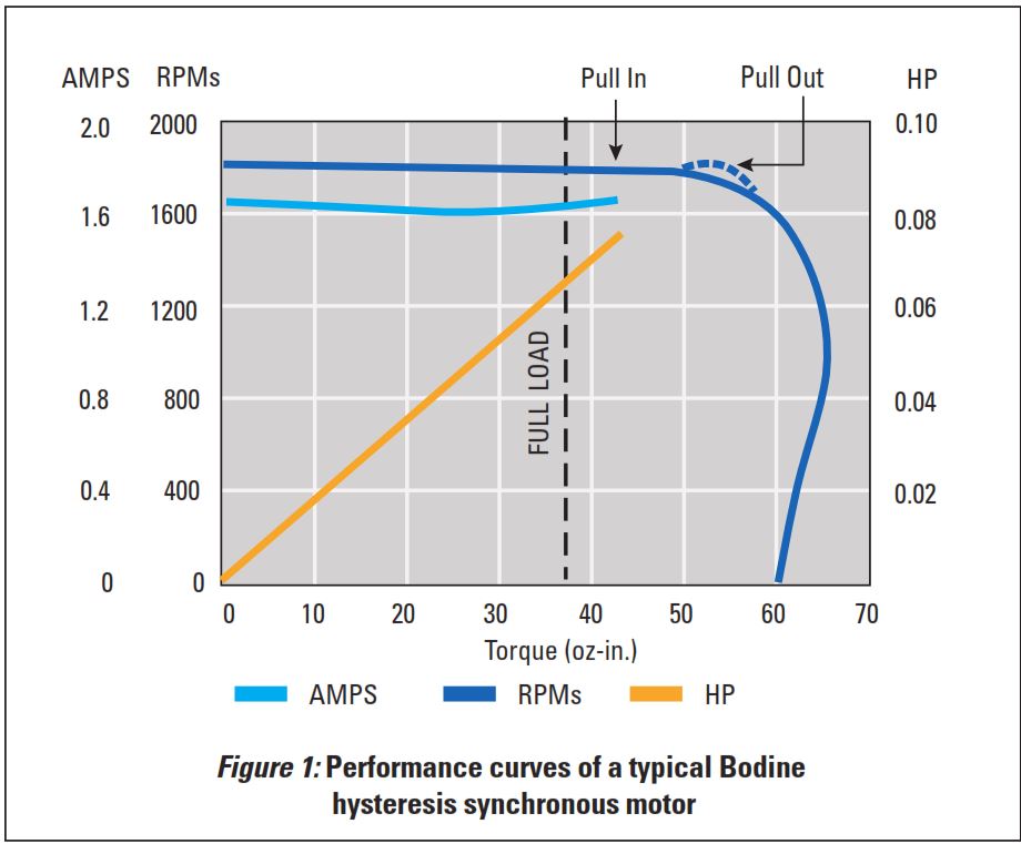
There are two common types of small synchronous AC induction motors, classified according to the type of rotor used:
(1) hysteresis synchronous motors
(2) reluctance synchronous motors
1. Hysteresis-type AC synchronous motors: Unlike squirrel-cage rotor AC induction motors, this motor type develops torque because of the magnetic hysteresis loss induced in its permanent magnet alloy rotor core. Although the stator in a hysteresis synchronous design is wound much like that of the conventional squirrel cage motor, its rotor is made of a heat-treated cast permanent magnet alloy cylinder (with a nonmagnetic support) securely mounted to the shaft. The motor’s special performance characteristics are associated with its rotor design. The rotor starts on the hysteresis principle and accelerates at a fairly constant rate until it reaches the synchronous speed of the rotating field. Instead of the permanently fixed poles found in the rotor of the reluctance synchronous design, hysteresis rotor poles are “induced” by the rotating magnetic field. During the acceleration period, the stator field will rotate at a speed faster than the rotor, and the poles which it induces in the rotor will shift around its periphery. When the rotor speed reaches that of the rotating stator field, the rotor poles will take up a fixed position. Like the reluctance synchronous motor, the coupling angle in hysteresis motors is not rigid, and if the load is increased beyond the capacity of the motor, the poles on the periphery of the rotor core will shift. If the load is then reduced to the “pull-in” capacity of the motor, the poles will take up fixed positions until the motor is again overloaded or stopped and restarted. The hysteresis rotor will “lock-in” at any position, in contrast to the reluctance rotor which has only the “lock-in” points corresponding to the salient poles on the rotor.
2. Reluctance Synchronous: A variation on the classic squirrel cage rotor, the reluctance synchronous rotor is modified to provide areas of high reluctance. 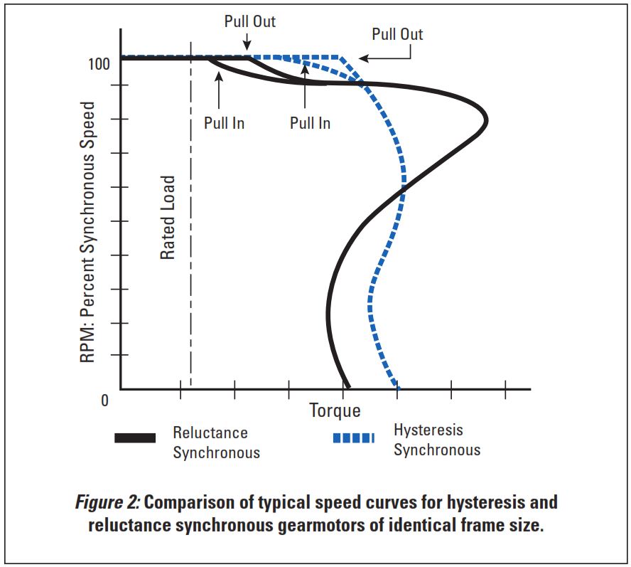
This may be done by designing notches (or flats) in the rotor periphery. The number of notches will correspond to the number of poles in the stator winding. The sections of the rotor periphery between the high reluctance areas are known as salient poles. Since these poles create a low reluctance path for the stator flux, they are attracted to the poles of the stator field.
The reluctance synchronous rotor starts and accelerates like a regular squirrel cage rotor, but as it approaches the rotational speed of the field, a critical point is reached where there is an increased acceleration and the rotor “snaps” into synchronism with the stator field. If the load (particularly inertial) is too great, the motor will not reach synchronous speed. Motor “pull-in” torque is defined as the maximum load that the motor can accelerate and pull into synchronism at rated voltage and frequency. An applied load greater than the rated “pull-in” torque will prevent the motor from pulling the load into synchronism and will result in rough, non-uniform operation.
The phase relationship between the poles of the rotating field and the rotor is known as the coupling angle, expressed in mechanical degrees. This coupling angle is not rigid, but will “increase” with an increase in load. At no load, the rotor poles will line up with the field poles and the coupling angle is considered to be zero.
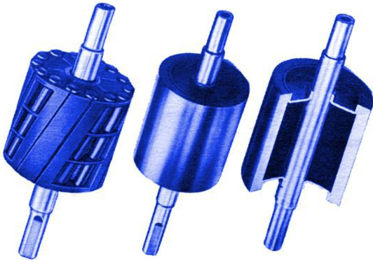
Fig. 3: Comparison of a typical reluctance synchronous rotor (left) and hysteresis synchronous rotors (center and right).
When a load is applied to reluctance synchronous motors, the magnetic lines of force coupling the rotor to the stator field are stretched, increasing the coupling angle. If the load is increased beyond the motor’s capability, the magnetic coupling between the rotor poles and stator field will break, and the rotor will “pull out” of synchronism. “Pull-out” torque is defined as the Maximum torque the motor can deliver at synchronous speed. Reluctance synchronous motors are available as AC 3-phase (inverter duty) designs, as well as single-phase versions in split-phase (with centrifugal start switch), CS (capacitor start) and PSC (permanent split capacitor) configurations. These motors have characteristics comparable to their non-synchronous counterparts using the same types of stator windings. For comparable output in a given frame size, the three-phase or PSC reluctance synchronous motor will provide quieter operation and more nearly uniform angular velocity than the split-phase or CS reluctance synchronous motor.
As shown in Figure 3, the reluctance rotor can be skewed to improve smoothness of operation.
Applications:
Like the reluctance synchronous type, hysteresis synchronous AC motors are used in equipment that requires accurately maintained (fixed) speed. Typical applications are timing mechanisms or drives requiring a constant relationship with time such as chart plotters, acoustical equipment, clocks and disc drives. The hysteresis type motor offers advantages over the reluctance type motor where noise levels must be low, load inertia tends to be high, or where two or more synchronous speeds are required without resorting to more advanced electronic speed controls. 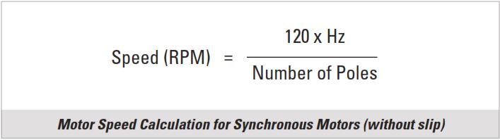
Standard fixed-speed AC motors are available up to 1/8 HP at 1800 (4-pole) and 3600 RPM (2-pole), 60 Hz, single phase. Speeds of 600, 900, and 1200 RPM are also available in certain frame sizes. Dual speed design options such as 600/1200, 900/1800 and 1800/3600 RPM for 60 Hz, single phase are also possible. Other dual speed and 3-speed combinations are available as custom (built-to-order) solutions, as well as motors and gearmotors for other voltages, frequencies and ratings, including 3-phase (inverter duty) gearmotors that operate at synchronous speed.
Advantages:
Synchronous motors operate at a constant (fixed) speed determined by the number of stator poles and the frequency of the power supply. Within the limitations of “pull-out” torque and no variation in line frequency, the speed can be considered constant. Inverter duty (3-phase) models can operate at variable speed, dependent on the output frequency from the AC speed control (VFD = variable frequency drive).
Hysteresis synchronous motors, with their uniform acceleration characteristics, can pull into synchronism any load that is within their capacity to start and accelerate.
Disadvantages:
Synchronizing characteristics of the reluctance motor requires increased acceleration of the rotor at the critical point when it approaches the rotational speed of the field. For this reason, it is possible that while the reluctance motor may easily start a high inertia load, it may not be able to accelerate the load enough to pull it into synchronism. Therefore it is important that when applying synchronous motors, to be certain that they will accelerate the loads to synchronous speed under the most adverse load and voltage conditions.
Conclusion:
Synchronous fixed-speed gearmotors or motors are ideal for applications where the load needs to be driven at an exact rate of speed, and where it is desired to not control the motor speed by means of an AC speed control (VFD). For a given horsepower, synchronous motors are usually slightly larger and cost more than non-synchronous motor or gearmotor, but they don’t require a costly speed control.
Synchronous variable-speed AC gearmotors and motors are ideal for applications where multiple drive motors are operated from one AC speed control (VFD). Because each motor or gearmotor will run at the exact same output speed, multiple axes can operate in synchronism without the need for a feedback device (encoder) or servo drive system. If multiple AC synchronous gearmotors are operated from one inverter drive (VFD), the sum of rated motor power for all synchronized axes must be equal or less the rated output power of the VFD. The same applies to the continuous current rating of the inverter — when multiple gearmotors are powered by one VFD, the continuous current rating of the inverter must be equal to or higher than the sum of the individual motor currents.
Application Example: Four (4) synchronous inverter duty (variable speed) 30R-D gearmotors drive the (4) ink metering pumps in a large newspaper printing press. For custom gearmotor solutions like this one, please contact our engineering team.

![]()
Copyright Bodine Electric Company © 06/2017. All rights reserved.