Standard AC motors provide low-cost, low maintenance power for almost any industrial application. However, they have limitations. They run at only one (fixed) speed, meaning sprockets, pulleys or a gearbox are required for speed reduction.
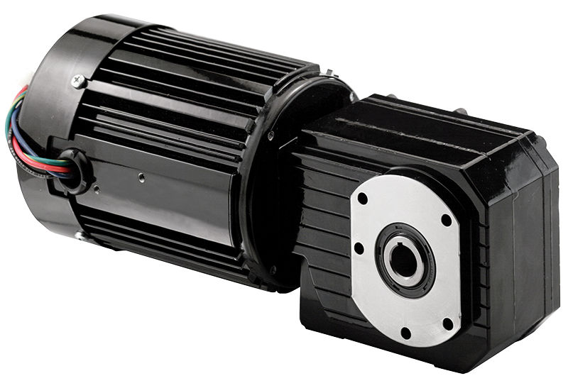
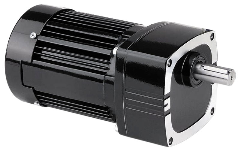
AC inverter-duty (variable speed) gearmotors feature either 230 VAC or 230/460 VAC AC 3-phase windings, specifically designed with inverter rated insulation. The special insulation system provides extra protection against high-voltage transients that PWM inverter drives can generate.


By converting the incoming 60 Hz AC power to a DC voltage, inverter drives (also called variable frequency drives) allow AC motors to run at variable speeds, and reduce the inrush of current when the motor starts to rotate. The DC voltage is “chopped” by power transistors (IGBTs) at high frequencies to simulate a sine wave that is then sent to the motor. Varying the output voltage and frequency of the control changes the speed of the motor.
AC Speed Control (VFD) Options

We offer three enclosure types with our AC speed controls. The AC stock controls require minimal set-up and no programming. Most Bodine inverter-duty gearmotor customers use our gearmotors in open-loop velocity control applications, like conveyors, feeders, or metering pumps. We also offer custom OEM solutions where we install encoders and other feedback devices to our inverter duty gearmotors and motors.
V/Hz inverters (basic)
This is the most basic type of drive. V/Hz drives use a pulse-width-modulation scheme to create an output roughly approximating a sine wave of variable frequency, with its amplitude, or voltage, proportional to set frequency. The speed range on V/Hz drives is limited and torque is not easily controlled.
Flux Vector Drive (open loop)
If more accurate and precise motion control is required, a Flux Vector Drive can be used, the basic set-up of these drives is “open-loop” (without an encoder); benefits are tighter speed control, wider speed range, and typically these digital drives come with advanced features like digital readouts, networking cards, and programming features.
Vector Drive System (closed loop)
The most accurate and servo-like performance is obtained from a closed loop vector drive system where an encoder feeds shaft position and rotation information back to the VFD. These closed-loop vector drive systems are more costly and complex systems to set up.

- Check the Line Frequency (Hz) Setting – We have seen situations where an inverter-duty gearmotor was running hot because the inverter was not set up properly to match the voltage and frequency ratings of the motor. Bodine inverter-duty gearmotors are rated at 230/460 V at 60 Hz. The default rating for most motors made for Europe or Asia is 50 Hz. If the inverter is set (or pre-set by the manufacturer) for a motor that is rated for 50 Hz, it will give the gearmotor too much voltage at each frequency setting and can lead to the gearmotor running hotter.
- Check the Nameplate Specifications – Make sure the input voltage to the inverter drive matches the inverter’s and the gearmotor’s voltage ratings and nameplate specifications. Check the user manual for details.
- Check the Voltage and Wiring Diagram – With dual-voltage rated inverter-duty gearmotors or motors with 8-10 motor leads, make sure to use the motor manufacturer’s wiring diagram to properly wire the gearmotor or motor for either 230VAC or 460VAC. Miss-wiring can lead to poor performance, not starting, or to motor or control damage.
- Check the Control Settings – There are many parameters that can be changed in the AC speed control that also affect motor performance and temperature. One example is the Torque Boost setting. At lower speed/frequency settings an inverter-duty gearmotor may not be able to produce the same torque that it can at a higher speed or frequency. The torque boost setting adjusts the output voltage at lower frequency to help the motor generate more torque at those lower speeds
Check these control settings before making any connections:
- Make sure the HP, voltage, and frequency jumpers match the motor nameplate and power source.
- If you are using a GFCI, select the correct jumper for the switching frequency.
- Select Constant Torque or Variable Torque depending on the application.
- Check the automatic restart setting
- Check the Run/Fault output contact settings and programming
5. Check the Rated Speed – Inverter-duty gearmotors will get hot, especially TEFC motors or gearmotors that operate between 10-90Hz. All our inverter-duty gearmotors are designed for continuous duty operation at their rated speed and frequency range (10-90Hz). Check the Safe Operating Area (SOA) graph for the gearmotor/motor to ensure that the gearmotor operates within its capabilities.
To download this blog article as a PDF, please click here.
Copyright Bodine Electric Company © 05/2020. All rights reserved.