Home > Support > Literature > User Manuals

MAINTENANCE - Gearmotor and Motor Safety - Installation Information
Bodine Lit. P/N 07400045.rev.i provides information on Product Safety, Installation and Maintenance of most Bodine stock Gearmotor and Motor products. AC Induction, Permanent Magnet DC and Brushless DC. If you have additional questions, please contact an Authorized Bodine Distributor, or e-mail us at: service@bodine-electric.com (PDF last updated 05/2014)
Download PDFE-mail this document to a friend
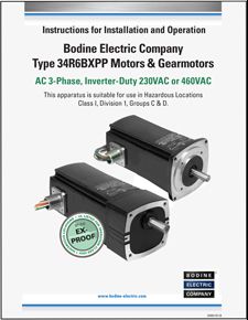
AC - 07401151.B Bodine C1D1 Ex-Proof AC Inverter-Duty 34R6-FX Gearmotor and 34R6 Motor User-Manual
Class I/Division 1 AC inverter-duty ex-proof gearmotors and motors are engineered to be used in environments where ignitable concentrations of flammable gases, vapors or liquids are likely to exist under normal operating conditions. P/N 07401151.Rev.B
Download PDFE-mail this document to a friend
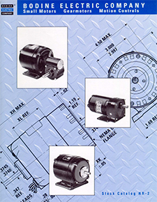
Obsolete N-Frame Products / Catalog NR-2 (2000)
Our "NR-2" catalog was created in the late 1990s to assist "N-Frame" motor and gearmotor customers with the transition from the now obsolete N-Frame gearmotors to newer Bodine products. Please call our customer support team if you need assistance. 773-478-3515 or info@bodine-electric.com
Download PDFE-mail this document to a friend
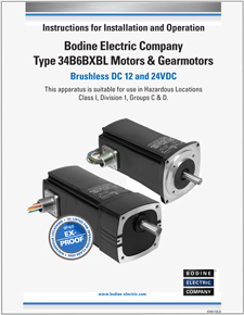
BLDC - 07401155.B Bodine C1D1 Ex-Proof Brushless DC 34B6-FX Gearmotor and 34B6 Motor User-Manual
Class I/Division 1 brushless DC ex-proof gearmotors and motors are engineered to be used in environments where ignitable concentrations of flammable gases, vapors or liquids are likely to exist under normal operating conditions. P/N 07401155.Rev.B (last update 06/2021).
Download PDFE-mail this document to a friend
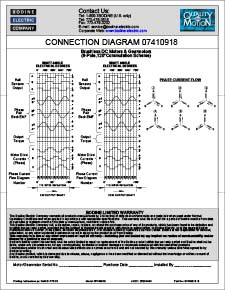
Connection Reference Table for BLDC C1/D1 Stock 8-pole, 120° Comm Gearmotors and Motors 07410918
Connection reference table for the hall sensor output, phase current and state for 8-pole, 120-degree commutation BLDC Class I/Div 1 ex-proof motors, and 34B6-FX gearmotors with EVEN number of gear stages (-FX2 or -FX4). Download to view this resource. Lit number 07410918.B (last update 05/2021).
Download PDFE-mail this document to a friend
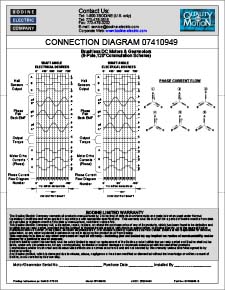
Connection Reference Table for BLDC C1/D1 Stock 8-pole, 120° Comm Gearmotors 07410949 (odd stages)
Connection reference table for the hall sensor output, phase current and state for 8-pole, 120-degree commutation BLDC Class I/Div 1 ex-proof 34B6-FX gearmotors with ODD number of gear stages (-FX1 or –FX3). Download to view this resource. Lit number 07410949.B (last update 05/2021).
Download PDFE-mail this document to a friend
AC - 07401080.D Pacesetter OEM Series AC Speed Controls - Open Chassis / IP-00
Manual P/N 07401080 Rev.D (PDF). This file is a new version of the printed user manual that is shipped and packaged with Bodine stock models 2982, 2983, 2984, and 2987. These products are RoHS compliant. [Updated 05/2011]
Download PDFE-mail this document to a friend
AC - 07410827.B Pacesetter Model 2998 - Installation & Operation Manual - NEMA-1 / IP-40
This NEMA-1 / IP-40, basic AC speed control operates our line of PACESETTER variable-speed, three-phase gearmotors and motors. Model 2998 operates from single-phase, 115 or 208-230 VAC line voltage. It is designed to power a wide range of 230 VAC, 50 or 60 Hz, inverter-duty, 3-phase gearmotors and motors; rated up to 1 HP (746 Watts). The control is simple to operate and requires no programming. This control is designed for stand-alone operation. Manual P/N 07410827B. [05/2011].
Download PDFE-mail this document to a friend
AC- 07401117.B - Pacesetter Model 2999 - AC Inverter Manual - NEMA-4X / IP-65
Download to view this resource
Download PDFE-mail this document to a friend
BL - 07401104C - 12VDC BLDC PWM SPEED CONTROLS; MODEL 3904
Compact, Low-Cost, Ideal for Battery or Solar Power Applications. Designed and Manufactured by Bodine Electric Company. This PDF file is a copy of the printed user manual that is packaged with our stock model 3904. Input voltage: 12-14VDC. Output: 0-12VDC or 0-24VDC. Commutation angle is 60°. Bodine literature no. 07401104C (04/2024).
Download PDFE-mail this document to a friend
BL - 07401105F - 12VDC AND 24VDC BLDC PWM SPEED CONTROLS; MODELS 3908, 3909 and 3919
Compact, Low-Cost, Ideal for Battery or Solar Power Applications. Designed and Manufactured by Bodine Electric Company. This PDF file is a copy of the printed user manual that is packaged with our stock models 3908, 3909 and 3919. Input voltage: 12-14VDC (mod no. 3908, 3919), 24-35VDC (mod no. 3909). Output: 0-12VDC or 0-24VDC (dependent on model; up to 95% of input). Commutation angle for models 3919 is 120°. Bodine literature no. 07401105F (04/2024).
Download PDFE-mail this document to a friend
![BL - 07401072 INTEGRAmotor 24V BLDC [type 22B/FV or 34B/FV] Brushless DC Motors and Gearmotors with Built-in Speed Control and Feedback [digital/PWM input] BL - 07401072 INTEGRAmotor 24V BLDC [type 22B/FV or 34B/FV] Brushless DC Motors and Gearmotors with Built-in Speed Control and Feedback [digital/PWM input]](/core/files/bodineelectric/resources/e851a6320d8012383a6b0458904893bf.jpg)
BL - 07401072 INTEGRAmotor 24V BLDC [type 22B/FV or 34B/FV] Brushless DC Motors and Gearmotors with Built-in Speed Control and Feedback [digital/PWM input]
The "22B/FV" INTEGRAmotors combine a 24VDC Brushless DC Motor or Gearmotor with a built-in, open loop, voltage mode PWM controller, accepting PWM input from an external motion or speed controller, also featuring amplifier enable, along with direction input, dynamic braking, and a built-in, 256 PPR, 2-channel encoder. P/N 07401072.Rev.A
Download PDFE-mail this document to a friend
![BL - 07401034.D INTEGRAmotor 24V BLDC [type 22B/SR] Brushless DC Motors and Gearmotors with Built-in Speed Control [analog input] BL - 07401034.D INTEGRAmotor 24V BLDC [type 22B/SR] Brushless DC Motors and Gearmotors with Built-in Speed Control [analog input]](/core/files/bodineelectric/resources/74627f0d7ae8255a77b2c7a89f3b1629.jpg)
BL - 07401034.D INTEGRAmotor 24V BLDC [type 22B/SR] Brushless DC Motors and Gearmotors with Built-in Speed Control [analog input]
This PDF file is a copy of the recently updated printed user manual P/N 07401034.D that is packaged with our 22B/SR stock INTEGRAmotor models. The "SR" type INTEGRAmotors feature an analog interface option. New Rev.D, Oct. 2010.
Download PDFE-mail this document to a friend
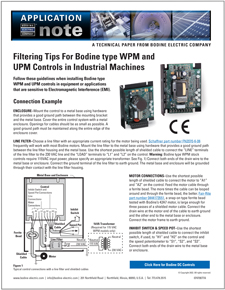
DC - 07470077.A Filtering Tips For Bodine type WPM and UPM Controls in Industrial Machines
This PDF provides guidelines for installing Bodine type WPM and UPM controls in equipment or applications that are sensitive to Electromagnetic Interference (EMI). Bodine literature no. 07470077A. Updated 06/2022.
Download PDFE-mail this document to a friend
![BL - 07401116.C INTEGRAmotor 12 or 24V BLDC [type 34B/SR-WX] Gearmotors with Built-in Speed Control [analog input] BL - 07401116.C INTEGRAmotor 12 or 24V BLDC [type 34B/SR-WX] Gearmotors with Built-in Speed Control [analog input]](/core/files/bodineelectric/resources/7dc52871031214e2c5fdcd907394af89.jpg)
BL - 07401116.C INTEGRAmotor 12 or 24V BLDC [type 34B/SR-WX] Gearmotors with Built-in Speed Control [analog input]
This PDF file is a copy of the printed user manual P/N 07401116.B that is packaged with our 34B/SR-WX stock INTEGRAmotor models. The "SR" type INTEGRAmotors feature an analog interface option. New Rev.C, July 2020.
Download PDFE-mail this document to a friend
BL - 07400185J-NEW ratings for Model 3907- 24VDC Brushless DC Control - Chassis, Low-Voltage (up to 3/8 HP)
This PDF file is a copy of the recently updated user manual for our low-voltage, 24 VDC, brushless DC (ECM) stock control models 3905 and 3907. *NEW* ratings for model 3907 (board re-design): runs our stock BLDC, type 34B6 motors and gearmotors, up to 3/8 HP. RoHS compliant, UR and CSA marked. Bodine literature no. 07400185J (04/2024).
Download PDFE-mail this document to a friend
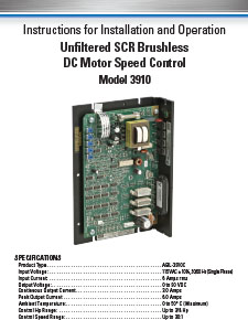
BL - 07400210.B - Model 3910 - BLDC Motor Speed Control, Chassis, Unfiltered
This PDF file is a copy of the printed user manual that is packaged with our stock model 3910. Input voltage: 115VAC, 50/60Hz, 1-phase. Output: unfiltered 0-90VDC (our 2500 RPM rated BLDC stock motors and gearmotors will run at 1750 RPM, at 100% speed. A lower cost alternative to our filtered 115VAC-in BLDC controls. Bodine literature no. 07400210.rev.B (05/2012).
Download PDFE-mail this document to a friend
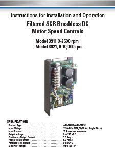
BL - 07400211.C - Models 3911 & 3921 BLDC Motor Speed Controls - Chassis, Filtered SCR
This PDF file is a copy of the printed user manual that is packaged with our stock models 3911 and 3921. Control input voltage: 115VAC, 50/60Hz, 1-phase. Output: filtered 0-130VDC. Bodine literature no. 07400211C (01/2020).
Download PDFE-mail this document to a friend
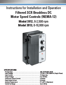
BL - 07400212.C - Models 3912 & 3913 BLDC Motor Speed Controls - Filtered SCR, NEMA-12
This PDF file is a copy of the updated printed user manual P/N 07400212.C that is packaged with stock models 3912 and 3913. Type ABL, Filtered SCR Controls, NEMA-12 Enclosure. 115VAC, 50/60Hz input; 0-130 VDC output. Bodine literature no. 07400212C. (08/2019).
Download PDFE-mail this document to a friend
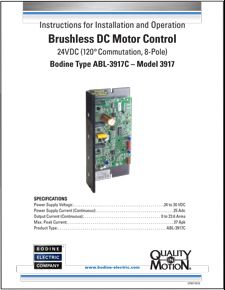
BL - 07401161.A - Model 3917 - User-manual-24VDC-BLDC-Chassis-Control
This PDF file is a copy of the printed user manual that is packaged with our stock models 3917. Control input voltage: 24-30VDC. Output: 0-24VDC. Bodine literature no. 07401161B (04/2024).
Download PDFE-mail this document to a friend
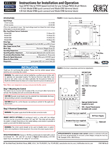
DC - 07401106.B - Models 0786, 0787, 0788 & 0789 PWM Motor Speed Controls Type "WPM" 12V and 24V
Our type WPM motor speed controls operate from a DC power supply or from a battery -- Input Voltage Range: 12-14 VDC or 24-35 VDC (dependent on model). Models 0788 and 0789 drive Bodine 24V PMDC motors and gearmotors up to 1/3 HP. Models 0786 and 0787 drive custom 12V PMDC motors and gearmotors. E-mail to info@bodine-electric.com for details. RoHS compliant. cURus. Bodine literature no. 07401106.rev.B (10/2017).
Download PDFE-mail this document to a friend
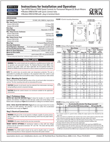
DC - 07400209.E - Models 0780, 0781, 0783 and 0784 Type "WPM"Chassis, filtered Motor Speed Controls [115VAC Input]
This PDF file is an updated version of our printed user manual that is packaged with stock models 0780, 0781, 0783 and 0784. Bodine type "WPM", filtered PWM speed controls for Permanent Magnet DC (PMDC) gearmotors and motors. Input: 115VAC +/- 10%, 50/60 Hz, single-phase. Output: 0-130 VDC. Bodine lit no. 07400209E, updated 06/2022.
Download PDFE-mail this document to a friend
DC - 07401107.A Model 0794 - type "WPM" Enclosed, NEMA-1, filtered PWM control with Dynamic Braking
This PDF file is a current version of the printed user manual P/N 07401107.A, that is packaged with stock models 0794. This Bodine type "WPM", filtered PWM speed control for Permanent Magnet DC (PMDC) gearmotors and motors includes a Forward-Brake-Reverse (FBR) switch for Dynamic Braking. NEMA-1/IP-20 enclosure. Input: 115VAC +/- 10%, 50/60 Hz, single-phase. Output: 0-130 VDC. Designed and manufactured by Bodine Electric Company. Marked cURus and RoHS. Made in the U.S.A.
Download PDFE-mail this document to a friend
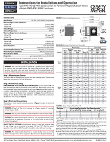
DC - 07400213.C Models 0790 / 0791 - DC Control - "WPM" Enclosed, NEMA-1, filtered PWM controls
This PDF file is a current version of the printed user manual P/N 07400213.C, that is packaged with stock models 0790 and 0791. Bodine type "WPM", filtered PWM speed controls for Permanent Magnet DC (PMDC) gearmotors and motors. NEMA-1 / IP-40 enclosure. Input: 115VAC +/- 10%, 50/60 Hz, single-phase. Output: 0-130 VDC. Designed and manufactured by Bodine Electric Company. Marked cURus and RoHS. Made in the U.S.A. - Available Worldwide!
Download PDFE-mail this document to a friend
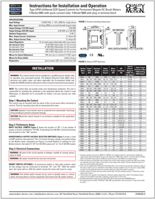
DC - 07400205.D Type "UPM" DC Motor Speed Control Models 0865 & 0866 - Chassis, Unfiltered SCR Control (0-90 or 0-180 VDC out)
This PDF file is a copy of the printed user manual that is packaged with stock models 0865 and 0866. Input Voltage: 115/230 VAC +/- 10%, 50/60 Hz, single phase. Output Voltage (115 VAC Input): 0-90 VDC. Output Voltage (230 VAC Input): 0-90 VDC or 0-180 VDC. Bodine lit no. 07400205.D, updated 06/2022.
Download PDFE-mail this document to a friend
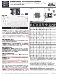
DC - 07400208.C Type "UPM" DC Motor Speed Control Model 0867 - NEMA-1, Unfiltered SCR Control (0-90 VDC out)
This PDF file is a copy of the printed user manual that is packaged with stock models 0867. Input Voltage: 115VAC +/- 10%, 50/60 Hz, single phase. Output Voltage: 0-90 VDC. Bodine lit no. 07400208.C, updated 07/2019)
Download PDFE-mail this document to a friend
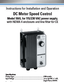
DC - 07401043.D Type "UPM" DC Motor Speed Control, Model 1865, 115 or 230VAC, 50/60Hz input
Instructions for Installation and Operation of stock model 1865, a PMDC motor speed control that is housed in a NEMA 4 enclosure. Input: 115 or 230 VAC +/- 10%, 50/60 Hz, single-phase. Output: 0-90 VDC or 0-180 VDC. With built-in line filter for "CE". Also cURus marked, and RoHS compliant. Designed and manufactured by Bodine Electric Company. Made in the U.S.A. - available Worldwide! Bodine lit no. 07401043D, updated 07/2019)
Download PDFE-mail this document to a friend
DC - 07400156.J - Type FPM, DC Chassis Controls with or without FBR
This manual provides information for installing and operating Bodine type FPM controls with or without the optional electronic Forward-Brake-Reverse (FBR) board. Although the instructions are specific to open chassis controls, they can be applied to enclosed models as well. Input: 115VAC, 50/60Hz, 1-phase; Output: 0-130 VDC (filtered, FF =1.0). Bodine literature no. 07400156.rev.J (01/2024).
Download PDFE-mail this document to a friend
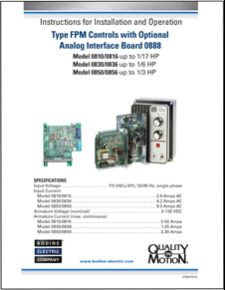
DC - 07400157.H - Type-FPM Controls with Analog Interface Board
This manual contains the basic information needed to operate a Bodine Type-FPM SCR control with Analog Interface Card. It is organized in a systematic, step-by-step fashion so that the system may be set up safely in the shortest possible time. Bodine literature no. 07400157.rev.H (1/2024).
Download PDFE-mail this document to a friend
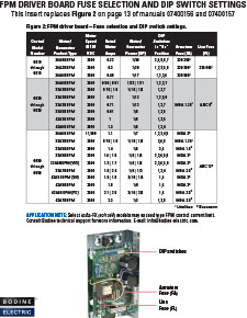
DC - 07401109.B - Updated DIP Switch Info for FPM Control User Manuals
This PDF provides updated DIP switch settings for Bodine FPM Controls. It replaces Fig.2 on page 13 in Bodine FPM user manuals 07400156 and 07400157. Bodine literature no. 07401109.rev.B (04/2013). Added info for WX and FX models.
Download PDFE-mail this document to a friend
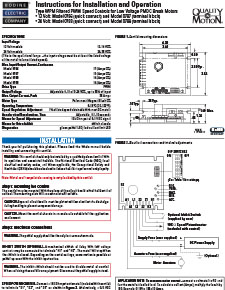
DC- 074401106.B - Model 0786 type "WPM" Low Voltage PWM DC Motor Speed Controls Installation Instructions
Download to view this resource
Download PDFE-mail this document to a friend
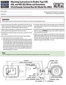
ACC - 07400067.E Model 0984, Die Cast Terminal Box Kit, IP-44
Rugged die cast terminal box kit that allows to upgrade most of our PMDC and AC motors and gearmotors to conform with IP-44 requirements. Lit No. 07400067.E (last update 03/2012).
Download PDFE-mail this document to a friend
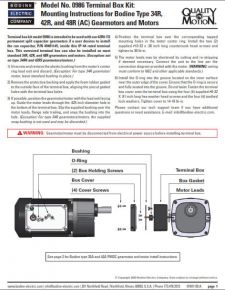
ACC - 07401150 Model 0986 Large Terminal Box Kit Installation Instructions
This larger terminal box is intended to be used with our type 42R-FX, permanent split capacitor (PSC) gearmotors, and allows to mount the large cylindrical run capacitor inside the t-box. The terminal box kit can also be installed on most of our standard 33A and 42A (PMDC), and 34R, 42R and 48R (AC) gearmotors and motors if IP-44 is required, or if our standard terminal box, model 0984 is not large enough. Bodine Literature number 07401150B (last update 6/2024).
Download PDFE-mail this document to a friend
![ACC - 07400090.B Models 0977 (33A) & 0978 (42A) Protection Kit for 33A and 42A [PMDC] Gearmotors and Motors ACC - 07400090.B Models 0977 (33A) & 0978 (42A) Protection Kit for 33A and 42A [PMDC] Gearmotors and Motors](/core/files/bodineelectric/resources/11748a312dba590658fca5fbe75fda7d.jpg)
ACC - 07400090.B Models 0977 (33A) & 0978 (42A) Protection Kit for 33A and 42A [PMDC] Gearmotors and Motors
This IP protection kit is intended for Bodine type 33A and 42A gearmotors and motors that don't have a terminal box installed. Lit No 07400090.B (last update 03/2020).
Download PDFE-mail this document to a friend
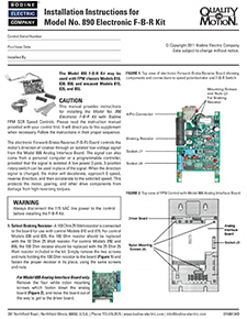
ACC - 07400134.B - Model No. 0890 Electronic F-B-R Kit - Installation Instructions
This PDF file is the latest revision of our installation instructions for stock model 0890 (F-B-R = Forward-Brake-Reverse kit). Bodine Literature number 07400134B (updated 03/2020).
Download PDFE-mail this document to a friend
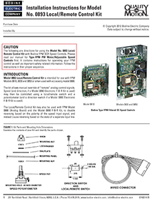
ACC - 07400141.B - Model 0893 Local/Remote Switch Kit for Bodine FPM Speed Controls - User Instructions
Installation instruction for using our Model No. 0893 Local/Remote Switch Kit with Bodine FPM SCR DC Speed Controls (Models 0810, 0830 and 0850; or when used with accessory model 0888). The kit allows manual override of “remote” analog control signals. Bodine Literature number 07400141B (last update 3/2020).
Download PDFE-mail this document to a friend
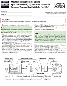
ACC - 07400170.D Model 1984, "Metric" Die Cast Terminal Box Kit (with terminal block)
Rugged die cast terminal box kit that allows to upgrade most of our PMDC and AC motors and gearmotors to conform with IP-44 requirements. In addition, this terminal box is shipped with a factory-installed terminal block. Bodine Literature number 07400170D (last update 3/2020).
Download PDFE-mail this document to a friend
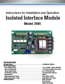
ACC - 07400187.D - Model 3984 Isolation and Interface Board
This PDF file is a copy of the updated and revised printed user manual for model 3984 -- our Isolation and Interface Board for DC and BLDC controls. P/N 07400187D (new rev.D, 03/2020)
Download PDFE-mail this document to a friend
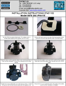
ACC - 07401102 Model 0976 Installation Instructions for 24A IP-44 brush ear cover kit
This IP-44 protection kit is intended for Bodine PMDC type 24A gearmotors and motors. Type 24A-60P planetary gearmotors are rated IP-65 and do not require this kit. Bodine Lit No. 07401102.B (02/2020).
Download PDFE-mail this document to a friend
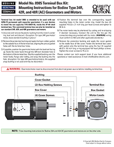
ACC - 07401113.A Model 0985, Die Cast Terminal Box, Oversized, IP-44
Oversized die cast terminal box kit that allows to upgrade most of our PMDC and AC motors and gearmotors to conform with IP-44 requirements. This t-box kit is intended to be used with our new 42R-FX, permanent split capacitor (PSC) gearmotors, and allows to mount the run capacitor inside the t-box. The t-box kit will also fit on many other stock products if an oversized terminal box is desired. Bodine Lit No. 07401113.A (03/2020).
Download PDFE-mail this document to a friend
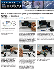
ACC - 07470039.A - How To Hook Up a 4-Wire-Reversible AC Motor or Gearmotor (and how to install a model 0984 Terminal box)
This application note outlines the basic steps for wiring up a 4-wire-reversible permanent split capacitor (PSC) motor or gearmotor from Bodine. Please download the correct connection diagram from our web site. Capacitor values vary from motor to motor. Check the motor nameplate or our web site for the required capacitance. Bodine Literature No. 07470039.A.
Download PDFE-mail this document to a friend
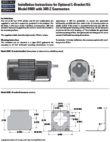
ACC - 07400118.B Model 0980 - L-Bracket Installation Instructions for 34R-Z Gearmotors
Installation instructions for Optional L-Bracket Kits Model 0980 with 34R-Z Gearmotors. Bodine Literature number 07400118B (last update 3/2020).
Download PDFE-mail this document to a friend
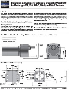
ACC - 07400055 Model 1968 - L-Bracket Installation Instructions for Metric type 30R, 33A, 30R-D, 24A-D, 24A-Z Gearmotors
Installation instructions for Optional L-Bracket Kits Model 1968 with Metric type 30R, 33A, 30R-D, 24A-D, 24A-Z Gearmotors. Bodine Literature number 07400055A (last update 3/2020).
Download PDFE-mail this document to a friend
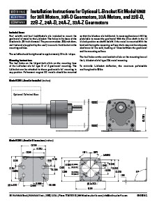
ACC - 07400024 Model 5968 - L-Bracket Installation Instructions for type 30R and 33A Motors, 30R-D, 22B-D, 22B-Z, 24A-D, 24A-Z, and 33A-Z Gearmotors
Installation instructions for Optional L-Bracket Kits Model 5968 with type 30R and 33A Motors, 30R-D, 22B-D, 22B-Z, 24A-D, 24A-Z, and 33A-Z Gearmotors. Bodine Literature number 07400024C (last updated 3/2020).
Download PDFE-mail this document to a friend

ACC - 07400007 Model 0969 and 1969 - L-Bracket Installation Instructions for type E, F, and Fx Gearmotors
Model 0969 and 0970 L-Bracket Installation Instructions for type E, F, and Fx Gearmotors. Bodine Literature number 07400007B (last update 03/2020).
Download PDFE-mail this document to a friend
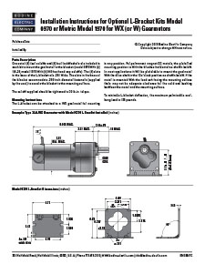
ACC - 07400047 Models 0970 and 1970 - L-Bracket Installation Instructions for Type W and WX Gearmotors
Models 0970 and 1970 L-Bracket Installation Instructions for Type W and WX Gearmotors
Download PDFE-mail this document to a friend

ACC - 07401160 Model 0979 - L-Bracket Installation Instructions for Type 34R and 34B Gearmotors (U.S./inch models only)
Model 0979 L-Bracket Installation Instructions for Type 34R and 34B Gearmotors (U.S./inch models only)
Download PDFE-mail this document to a friend
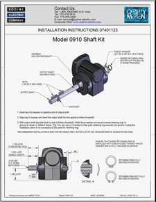
ACC - 07401123 MODEL 0910 SHAFT KIT / 1/2-INCH SINGLE SHAFT INSTALLATION INSTRUCTIONS FOR TYPE 3F/H GEARMOTORS
Model 0910 Shaft Kit Installation Instructions for type 3F/H gearmotors. Bodine Literature number 07401123A (last update 11/2020).
Download PDFE-mail this document to a friend
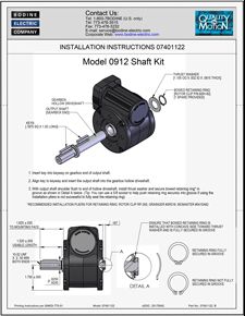
ACC - 07401122 MODEL 0912 SHAFT KIT / 5/8-INCH SINGLE SHAFT INSTALLATION INSTRUCTIONS FOR TYPE 5L/H GEARMOTORS
Model 0912 Shaft Kit Installation Instructions for type 5L/H gearmotors. Bodine Literature number 07401122B (last update 11/2020).
Download PDFE-mail this document to a friend
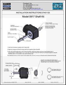
ACC - 07401125 MODEL 0917 SHAFT KIT / 3/4-INCH SINGLE SHAFT INSTALLATION INSTRUCTIONS FOR TYPE GB/H GEARMOTORS
Model 0917 Shaft Kit Installation Instructions for type GB/H gearmotors. Bodine Literature number 07401125B (last update 11/2020).
Download PDFE-mail this document to a friend
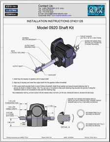
ACC - 07401128 MODEL 0920 SHAFT KIT / 1/2-INCH DOUBLE SHAFT INSTALLATION INSTRUCTIONS FOR TYPE 3F/H GEARMOTORS
Model 0920 Shaft Kit Installation Instructions for type 3F/H gearmotors. Bodine Literature number 07401128B (last update 11/2020).
Download PDFE-mail this document to a friend
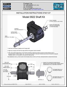
ACC - 07401127 MODEL 0922 SHAFT KIT / 5/8-INCH DOUBLE SHAFT INSTALLATION INSTRUCTIONS FOR TYPE 5L/H GEARMOTORS
Model 0922 Shaft Kit Installation Instructions for type 5L/H gearmotors. Bodine Literature number 07401127B (last update 11/2020).
Download PDFE-mail this document to a friend
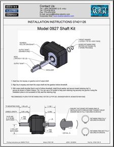
ACC - 07401126 MODEL 0927 SHAFT KIT / 3/4-INCH DOUBLE SHAFT INSTALLATION INSTRUCTIONS FOR TYPE GB/H GEARMOTORS
Model 0927 Shaft Kit Installation Instructions for type GB/H gearmotors. Bodine Literature number 07401126B (last update 11/2020).
Download PDFE-mail this document to a friend
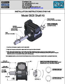
ACC - 07401145.A Model 0928 Shaft Kit / 5/8-Inch single shaft Installation instructions for Type GB/H Gearmotors
Installation instructions for Optional Shaft Kit Model 0928 for use with type 5L/H hollow shaft gearmotors. Bodine Literature number 07401145A (last update 3/2020).
Download PDFE-mail this document to a friend
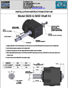
ACC - 07401146.A Model 0929 and 0930 Shaft Kit / single shaft Installation instructions for hypoid gearmotors
Installation instructions for Optional Shaft Kit Models 0929 and 0930 for use with hypoid gearmotors. Bodine Literature number 07401146A (last update 4/2020).
Download PDFE-mail this document to a friend
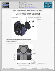
ACC - 07401129 MODEL 0950 COVER KIT INSTALLATION INSTRUCTIONS FOR TYPE 3F/H GEARMOTORS
Model 0950 Cover t Kit Installation Instructions for type 3F/H gearmotors. Bodine Literature number 07401129A (last update 11/2020).
Download PDFE-mail this document to a friend
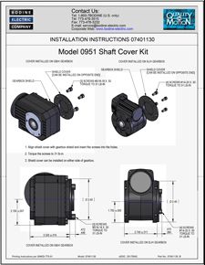
ACC - 07401130 MODEL 0951 COVER KIT INSTALLATION INSTRUCTIONS FOR TYPES 5L/H AND GB/H GEARMOTORS
Model 0951 Cover Kit Installation Instructions for type 5L/H and GB/H gearmotors. Bodine Literature number 07401130B (last update 11/2020).
Download PDFE-mail this document to a friend
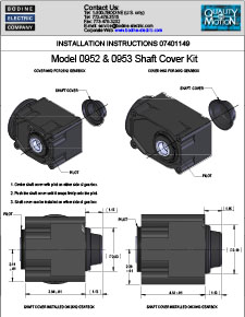
ACC - 07401149 Models 0952 and 0953 Shaft Cover Kit Installation Instructions for hypoid gearmotors
Installation instructions for Optional Shaft Cover Kit Models 0952 and 0953 for use with hypoid gearmotors. Bodine Literature number 07401149A (last update 4/2020).
Download PDFE-mail this document to a friend
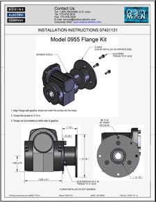
ACC - 07401131 MODEL 0955 FLANGE MOUNT KIT INSTALLATION INSTRUCTIONS FOR TYPE 3F/H GEARMOTORS
Model 0955 Flange Mount Kit Installation Instructions for type 3F/H gearmotors. Bodine Literature number 07401131A (last update 11/2020).
Download PDFE-mail this document to a friend

ACC - 07401132 MODEL 0956 FLANGE MOUNT KIT INSTALLATION INSTRUCTIONS FOR TYPES 5L/H AND GB/H GEARMOTORS
Model 0956 Flange Mount Kit Installation Instructions for types 5L/H and GB/H gearmotors. Bodine Literature number 07401132B (last update 11/2020).
Download PDFE-mail this document to a friend
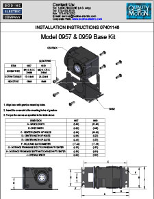
ACC - 07401148 MODELS 0957 and 0959 BASE MOUNT KIT INSTALLATION INSTRUCTIONS FOR HYPOID GEARMOTORS
Installation instructions for Optional Base Mount Kit Models 0957 and 0959 for use with hypoid gearmotors. Bodine Literature number 07401148A (last update 4/2020).
Download PDFE-mail this document to a friend
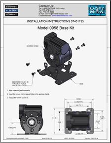
ACC - 07401133 MODEL 0958 BASE MOUNT KIT INSTALLATION INSTRUCTIONS FOR TYPE 5L/H GEARMOTORS
Model 0958 Base Mount Kit Installation Instructions for type 5L/H gearmotors. Bodine Literature number 07401133B (last update 11/2020).
Download PDFE-mail this document to a friend
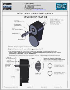
ACC - 07401157 Model 0932 Shaft Kit / 3/4-inch single shaft Installation Instructions for Type HG/H Gearmotors
Model 0932 Shaft Kit / 3/4-inch single shaft Installation Instructions for Type HG/H Gearmotors. Bodine Literature number 07401157A (last update 8/2021).
Download PDFE-mail this document to a friend
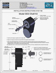
ACC - 07401158 Model 0933 Shaft Kit / 3/4-inch double shaft Installation Instructions for Type HG/H Gearmotors
Model 0933 Shaft Kit / 3/4-inch double shaft Installation Instructions for Type HG/H Gearmotors. Bodine Literature number 07401158A (last update 8/2021).
Download PDFE-mail this document to a friend
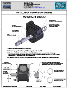
ACC - 07401168.A Model 0934 Shaft Kit / 3/4-inch Stainless Steel Single Shaft Installation Instructions for Type 5L/H Gearmotors
Download to view this resource
Download PDFE-mail this document to a friend
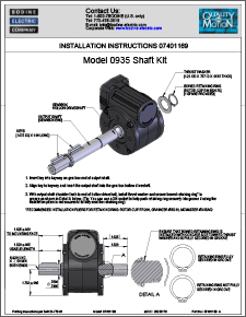
ACC - 07401169.A Model 0935 Shaft Kit / 3/4-inch Stainless Steel Double Shaft Installation Instructions for Type 5L/H Gearmotors
Download to view this resource
Download PDFE-mail this document to a friend
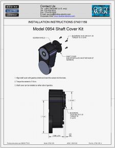
ACC - 07401159 Model 0954 Cover Kit Installation Instructions for Type HG/H Gearmotors
Model 0954 Cover Kit Installation Instructions for Type HG/H Gearmotors. Bodine Literature number 094011059A (last update 8/2021).
Download PDFE-mail this document to a friend
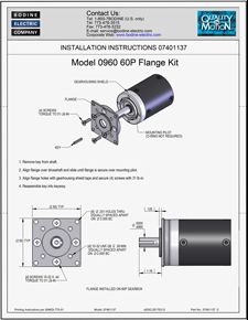
ACC - 07401137 MODEL 0960 FLANGE KIT INSTALLATION INSTRUCTIONS FOR TYPE 60P GEARMOTORS
Model 0960 Flange Mount Kit Installation Instructions for type 60P gearmotors. Bodine Literature number 07401137C (last update 11/2020).
Download PDFE-mail this document to a friend
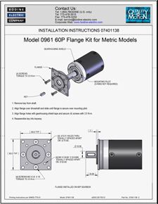
ACC - 07401138 MODEL 0961 FLANGE KIT INSTALLATION INSTRUCTIONS FOR TYPE 60P GEARMOTORS (METRIC)
Model 0961 Flange Mount Kit Installation Instructions for type 60P metric gearmotors. Bodine Literature number 07401138C (last update 11/2020).
Download PDFE-mail this document to a friend
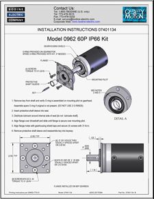
ACC - 07401134 MODEL 0962 FLANGE IP-66 SEAL KIT INSTALLATION INSTRUCTIONS FOR TYPE 60P GEARMOTORS
Model 0962 Flange IP-66 Mount Kit Installation Instructions for type 60P gearmotors. Bodine Literature number 07401134B (last update 11/2020).
Download PDFE-mail this document to a friend
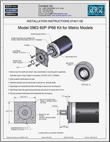
ACC - 07401136 MODEL 0963 FLANGE IP-66 SEAL KIT INSTALLATION INSTRUCTIONS FOR TYPE 60P GEARMOTORS (METRIC)
Model 0963 Flange IP-66 Mount Kit Installation Instructions for type 60P metric gearmotors. Bodine Literature number 07401136B (last update 11/2020)
Download PDFE-mail this document to a friend
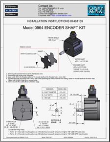
ACC - 07401139 MODEL 0964 ENCODER SHAFT KIT INSTALLATION INSTRUCTIONS
Model 0964 Encoder Shaft Kit Installation Instructions. Bodine Literature number 07401139C (last update 11/2020)
Download PDFE-mail this document to a friend
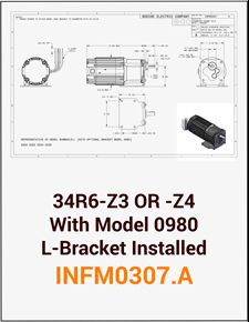
ACC - 34R6-Z3 or Z4 Gearmotor with Model 0980 L-Bracket installed INFM0307.A
Bodine type 34R6-Z3 or -Z4 gearmotors with Model 0980 L-bracket kit installed. Drawing provides shaft height dimension from mounting surface when this L-bracket kit is used.
Download PDFE-mail this document to a friend
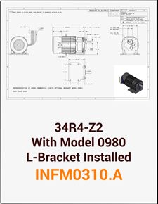
ACC - INFM0310.A 34R4-Z2 with Model 0980 L-Bracket installed
Bodine type 34R6-Z2 gearmotors with Model 0980 L-bracket kit installed. Drawing provides shaft height dimension from mounting surface when this L-bracket kit is used.
Download PDFE-mail this document to a friend
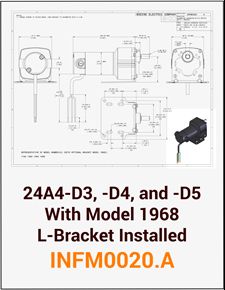
ACC - INFM0020.A 24A4-D3, -D4, and -D5 with Model 1968 L-Bracket installed
Bodine type 24A4-D3, D4, and D5 gearmotors with Model 1968 L-bracket kit installed. Drawing provides shaft height dimension from mounting surface when this L-bracket kit is used.
Download PDFE-mail this document to a friend
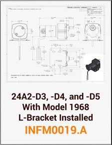
ACC - INFM0019.A 24A2-D3, -D4, and -D5 with Model 1968 L-Bracket installed
Bodine type 24A2-D3, -D4, and -D5 gearmotors with Model 1968 L-bracket kit installed. Drawing provides shaft height dimension from mounting surface when this L-bracket kit is used.
Download PDFE-mail this document to a friend
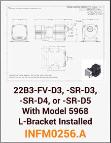
ACC - INFM0256.A 22B3-FV-D3, -SR-D3, -SR-D4, or -SR-D5 with Model 5968 L-Bracket installed
Bodine type 22B3-FV-D3, -SR-D3, -SR-D4, and -SR-D5 gearmotors with Model 5968 L-bracket kit installed. Drawing provides shaft height dimension from mounting surface when this L-bracket kit is used.
Download PDFE-mail this document to a friend
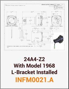
ACC - INFM0021.A 24A4-Z2 with Model 1968 L-Bracket installed
Bodine type 24A4-Z2 gearmotors with Model 1968 L-bracket kit installed. Drawing provides shaft height dimension from mounting surface when this L-bracket kit is used.
Download PDFE-mail this document to a friend
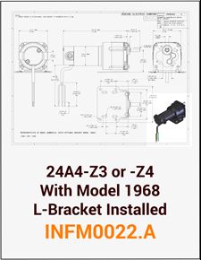
ACC - INFM0022.A 24A4-Z3 or -Z4 with Model 1968 L-Bracket installed
Bodine type 24A4-Z3 or -Z4 gearmotors with Model 1968 L-bracket kit installed. Drawing provides shaft height dimension from mounting surface when this L-bracket kit is used.
Download PDFE-mail this document to a friend
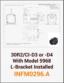
ACC - INFM0296.A 30R2/CI-D3 or -D4 with Model 5968 L-Bracket installed
Bodine type 30R2/CI-D3 or -D4 gearmotors with Model 5968 L-bracket kit installed. Drawing provides shaft height dimension from mounting surface when this L-bracket kit is used.
Download PDFE-mail this document to a friend
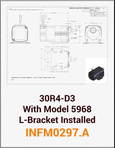
ACC - INFM0297.A 30R4-D3 with Model 5968 L-Bracket installed
Bodine type 30R4-D3 gearmotors with Model 5968 L-bracket kit installed. Drawing provides shaft height dimension from mounting surface when this L-bracket kit is used.
Download PDFE-mail this document to a friend
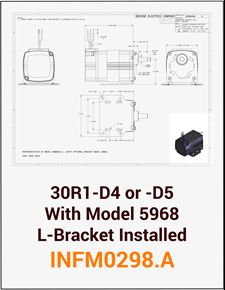
ACC - INFM0298.A 30R1-D4 or -D5 with Model 5968 L-Bracket installed
Bodine type 30R1-D4 or -D5 gearmotors with Model 5968 L-bracket kit installed. Drawing provides shaft height dimension from mounting surface when this L-bracket kit is used.
Download PDFE-mail this document to a friend
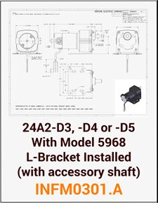
ACC - INFM0301.A 24A2-D3, -D4, or -D5 with Model 5968 L-Bracket installed (with Accessory Shaft)
Bodine type 24A2-D3, -D4, or -D5 gearmotors with Model 5968 L-bracket kit installed (with accessory shaft). Drawing provides shaft height dimension from mounting surface when this L-bracket kit is used.
Download PDFE-mail this document to a friend
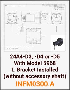
ACC - INFM0300.A 24A4-D3, -D4, or -D5 with Model 5968 L-Bracket installed (without Accessory Shaft)
Bodine type 24A4-D3, -D4, or -D5 gearmotors with Model 5968 L-bracket kit installed (without accessory shaft). Drawing provides shaft height dimension from mounting surface when this L-bracket kit is used.
Download PDFE-mail this document to a friend
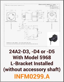
ACC - INFM0299.A 24A2-D3, -D4, or -D5 with Model 5968 L-Bracket installed (without Accessory Shaft)
Bodine type 24A2-D3, -D4, or -D5 gearmotors with Model 5968 L-bracket kit installed (without accessory shaft). Drawing provides shaft height dimension from mounting surface when this L-bracket kit is used.
Download PDFE-mail this document to a friend
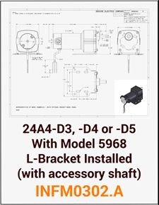
ACC - INFM0302.A 24A4-D3, -D4, or -D5 with Model 5968 L-Bracket installed (with Accessory Shaft)
Bodine type 24A4-D3, -D4, or -D5 gearmotors with Model 5968 L-bracket kit installed (with accessory shaft). Drawing provides shaft height dimension from mounting surface when this L-bracket kit is used.
Download PDFE-mail this document to a friend
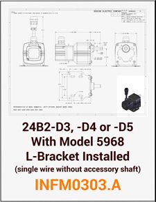
ACC - INFM0303.A 22B2-D3, -D4, or -D5 with Model 5968 L-Bracket installed (Single Wire without Accessory Shaft)
Bodine type 24B2-D3, -D4, or -D5 gearmotors with Model 5968 L-bracket kit installed (single wire without accessory shaft). Drawing provides shaft height dimension from mounting surface when this L-bracket kit is used.
Download PDFE-mail this document to a friend
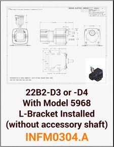
ACC - INFM0304.A 22B2-D3 or -D4 with Model 5968 L-Bracket installed (without Accessory Shaft)
Bodine type 24B2-D3 or -D4 gearmotors with Model 5968 L-bracket kit installed (without accessory shaft). Drawing provides shaft height dimension from mounting surface when this L-bracket kit is used.
Download PDFE-mail this document to a friend
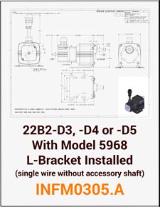
ACC - INFM0305.A 22B2-D3 or -D4 with Model 5968 L-Bracket installed (Single Wire with Accessory Shaft)
Bodine type 24B2-D3 or -D4 gearmotors with Model 5968 L-bracket kit installed (single wire with accessory shaft). Drawing provides shaft height dimension from mounting surface when this L-bracket kit is used.
Download PDFE-mail this document to a friend
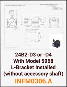
ACC - INFM0306.A 22B2-D3 or -D4 with Model 5968 L-Bracket installed (without Accessory Shaft)
Bodine type 24B2-D3 or -D4 gearmotors with Model 5968 L-bracket kit installed (without accessory shift). Drawing provides shaft height dimension from mounting surface when this L-bracket kit is used.
Download PDFE-mail this document to a friend
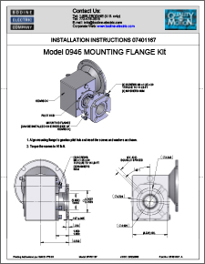
ACC - 07401167 Model 0946 Mounting Flange Kit Installation Instructions for Type 50JW/H Gearmotors
Download to view this resource
Download PDFE-mail this document to a friend
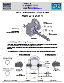
ACC - 07401166 Model 0945 Shaft Kit / 1-inch Stainless Steel Double-Extension Shaft Installation Instructions for Type 50JW/H Gearmotors
Download to view this resource
Download PDFE-mail this document to a friend
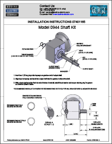
ACC - 07401165 Model 0944 Shaft Kit / 1-inch Stainless Steel Single-Extension Shaft Installation Instructions for Type 50JW/H Gearmotors
Download to view this resource
Download PDFE-mail this document to a friend
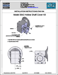
ACC - 07401164 Model 0943 Hollow Shaft Cover Kit Installation Instructions for Type 50JW/H Gearmotors
Download to view this resource
Download PDFE-mail this document to a friend
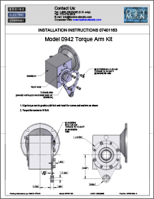
ACC - 07401163 Model 0942 Torque Arm Kit Installation Instructions for Type 50JW/H Gearmotors
Download to view this resource
Download PDFE-mail this document to a friend
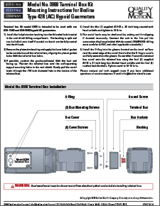
ACC - 07401162.A Model 0988 Terminal Box Kit Mounting Instructions for Type 42R (AC) Hypoid Gearmotors
This die cast terminal box kit was designed to fit on our new 42R, AC, three-phase, inverter-duty Hypoid gearmotors, type 42R6BERPP-25H2, and -30H3. The terminal box meets IP-66 with proper PG fitting and power cord installed (last update 6/2024).
Download PDFE-mail this document to a friend
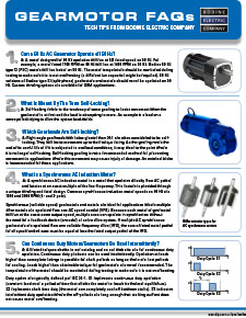
REF/CONNECTION - Gearmotor FAQs - Issue 1 / 2017
When you have worked with Fractional Horsepower (FHP) gearmotors for as long as we have, you encounter about every possible question there is! With this new FAQ document, we\'ll kick off a series of PDFs that will address the most frequently asked questions related to small gearmotors, motors and motor speed controls. Please contact our team if you have a technical question. We look forward to answering it for you. E-mail us at: info@bodine-electric.com, or call 773-478-3515.
Download PDFE-mail this document to a friend
REF/CONNECTION - 1-2-3 Motor and Gearmotor Selection Guide (Updated 11/2017)
This selection guide was designed to help you specify the best motor, gearmotor and control solution for your application. By considering three key design criteria, you can quickly select a drive system that should meet your application needs: (1) Determine the required speed and torque. (2) Select the appropriate motor type. (3) Select gear reducer, if needed. Bodine literature no. 07481011B.
Download PDFE-mail this document to a friend
![REF/CONNECTION How To Connect a 3-Wire-Reversible (Permanent Split Capacitor) Motor or Gearmotor [and how to wire a reversing switch] REF/CONNECTION How To Connect a 3-Wire-Reversible (Permanent Split Capacitor) Motor or Gearmotor [and how to wire a reversing switch]](/core/files/bodineelectric/resources/267d582602c9956b1dde35c728568fc0.jpg)
REF/CONNECTION How To Connect a 3-Wire-Reversible (Permanent Split Capacitor) Motor or Gearmotor [and how to wire a reversing switch]
This application note outlines the basic steps for wiring a 3-wire-reversible AC, permanent split capacitor (PSC) motor or gearmotor from Bodine. On page 2, we explain how to use a single pole, double throw toggle switch, with center-off, to reverse our 3-wire motors. Please download the correct connection diagram from our web site. Capacitor values vary from motor to motor. Check the motor nameplate or our web site for the required capacitance. Bodine Literature No. 07470048.A.
Download PDFE-mail this document to a friend
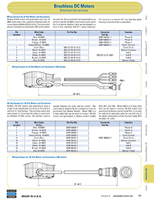
REF/CONNECTION - Brushless DC Electrical Connections
This PDF document describes the electrical connections for our brushless DC motors and gearmotors. Excerpt from our old product catalog (S-16). If you have questions about BLDC motor connections, please contact our Support Team: info@bodine-electric.com
Download PDFE-mail this document to a friend
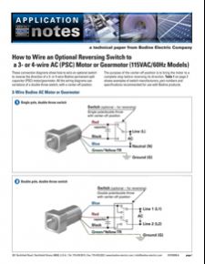
REF/CONNECTION - How To Connect a Reversing Switch to a 3-, or 4-Wire-Reversible (PSC) Motor or Gearmotor
This Application/Tech Note provides four (4) examples for how to reverse 3- and 4-wire reversible PSC gearmotors and motors from Bodine with a simple switch.
Download PDFE-mail this document to a friend
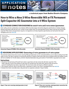
REF/CONNECTION - How To Connect a 3-Wire-Reversible WX or FX (Permanent Split Capacitor) Gearmotor into a 4-Wire System
This Application Note explains how to connect a new Bodine WX or FX (3-wire-reversible) single-phase AC Motor or Gearmotor into a piece of equipment that was designed (& wired) for a 4-wire-reversible motor or gearmotor. Please note that the motor run capacitor will also have to be changed. Bodine Literature No. 07470040.rev.A (09/2013). All rights reserved.
Download PDFE-mail this document to a friend
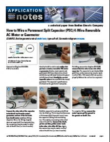
REF/CONNECTION - How To Hook Up a 4-Wire-Reversible AC Motor or Gearmotor (and how to install a model 0984 Terminal box)
This application note outlines the basic steps for wiring up a 4-wire-reversible permanent split capacitor (PSC) motor or gearmotor from Bodine. Please download the correct connection diagram from our web site. Capacitor values vary from motor to motor. Check the motor nameplate or our web site for the required capacitance. Bodine Literature No. 07470039.A.
Download PDFE-mail this document to a friend
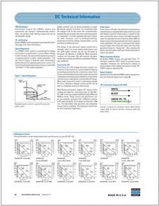
Bodine-PMDC-Motor-Gearmotor-Technical-Information
This PDF document contains technical information about our DC motors and controls, including connection diagram and performance curves. Excerpted from our product catalog.
Download PDFE-mail this document to a friend
Log in to download this resource
Sign in or register an account with us to get unlimited access to exclusive content like this resource.