All of Bodine’s potentiometers are one-turn pots. If you need any other type (i.e. multiple-turn pot), it must be sourced separately.
Technically, the answer is yes. However, if the continuous output current on your control is less than that of the motor’s nameplate rated current, you will run into current limit and will not get the full nameplate rated torque from the motor.
No, brushless DC motors cannot be run with an AC VFD. The brushless motor needs electronic commutation, and this will not be provided correctly from a VFD. The motor design will not work with a VFD. It may be possible, through some experimenting, to get the motor to turn, but there will be zero torque out.
Brushless DC (BLDC) gearmotors are typically quieter than PMDC gear motors or inverter-duty AC three-phase gearmotor and motor designs. PMDC gearmotors have carbon brushes that continuously “rub” on the commutator of the motor armature. This interaction, along with the DC power from an unfiltered SCR or PWM speed control can result in audible noise. Similarly, inverter-duty, variable speed AC motors and gearmotors emit some noise created by the PWM voltage supplied to the motor from the inverter (PWM speed control). Gear housing style and design, as well as the number of gear stages can also affect overall noise emitted from the gearmotor. Worm gearheads (right-angle gearmotors) are generally quieter than inline or parallel shaft gearmotors due to the differences in gear geometry and how the gear sets interact.
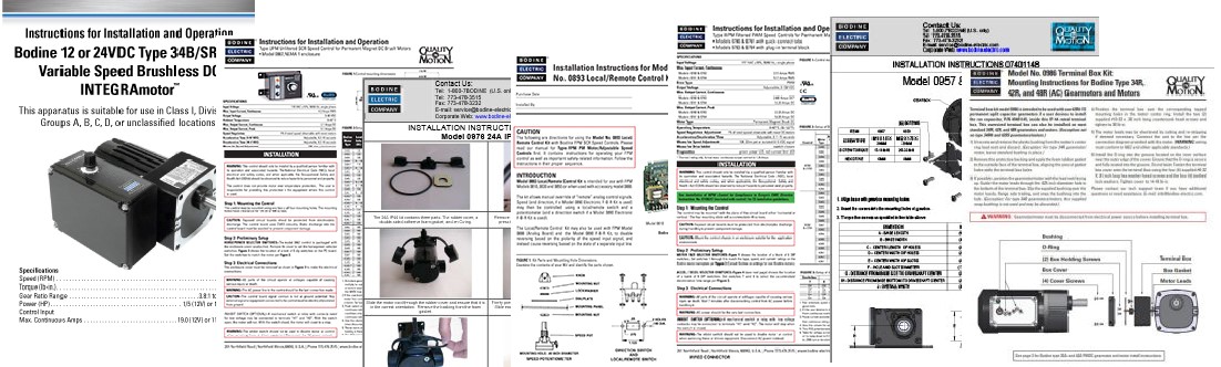
All our gearmotor, speed control, and gearmotor accessory user manuals, and our installation instructions can be downloaded from the Literature sections of our website. You can find them under the Support tab > Literature > User Manuals. We also offer a large collection of application notes that cover many frequently asked user questions. Also under the Support tab and in the Literature section are links to download our many product info sell sheets, our product SDS (safety data sheets) for gearmotor lubricants, and our main product catalog “S” and the Bodine Handbook.
Yes, it is possible to run more than one AC three-phase motor/gearmotor with one AC speed control (VFD).
Note: The motors/gearmotors must be AC 3-phase and inverter-duty. Second, the continuous output current of the speed control (variable frequency drive) must be greater than or equal to the sum of the rated motor currents.
AC Speed Control (VFD) Basics:
AC inverter-duty (variable speed) gearmotors feature either 230 VAC or 230/460 VAC AC 3-phase windings, specifically designed with an inverter rated insulation system. Our AC speed controls require minimal set-up and no programming. Most Bodine inverter-duty gearmotor customers use our gearmotors in open-loop velocity control applications, like conveyors, feeders, or metering pumps. The V/Hz inverters (VFDs) are the most basic type of drive. V/Hz drives use a pulse-width-modulation scheme to create an output roughly approximating a sine wave of variable frequency, with its amplitude, or voltage, proportional to set frequency. The speed range on V/Hz drives is limited and torque is not easily controlled.
PMDC Speed Control Basics:
Basic PMDC motor speed controls accomplish the conversion of AC power to DC with varying degrees of DC voltage “purity” (see FAQs on Form Factor). For proper control selection you’ll need to identify which performance criteria are important to your application. There are four basic types of PMDC speed controls.
1. The unfiltered half-wave Silicon Controlled Rectifier (SCR) control is the most basic design. The unfiltered full-wave SCR control places a single SCR in series with the DC motor’s armature winding. This converts the AC into DC by simply blocking the negative half cycle of the AC sine wave. The SCR control produces a fairly choppy output for the motor and only faintly resembles a true DC current.
2. The unfiltered full-wave SCR control improves on the unfiltered half-wave SCR control by adding another SCR and two diodes to form a bridge rectifier, instead of just blocking out the negative half cycle of the AC sine.
3. The filtered full-wave SCR control design utilizes a large filter capacitor that is placed across the output of the control. Since a capacitor stores energy during the rising portion of the AC sine wave and then discharges it slowly during the falling portion, it effectively smoothens out the choppy output current created by the switching of the SCRs. As a result, a smooth output current is produced that approximates pure DC.
4. A filtered Pulse Width Modulation (PWM) control uses a different method to produce a smooth output current that is comparable to that of a filtered full-wave SCR control. The AC supply is first rectified and filtered before it is switched on and off to vary the output voltage. In contrast, the filtered full-wave SCR control simultaneously rectifies and switches the AC supply, then filters it after switching.
See our Application Notes page for more details on Speed Control Selection: https://www.bodine-electric.com/application-notes/
BLDC Speed Control Basics:
In a brushless DC (BLDC) motor, the magnetic field rotates, while the BLDC motor rotor is equipped with high-energy permanent magnets (4- or 8-pole). Commutation (60° or 120°) occurs electronically by switching the (three-phase) stator current direction at precise intervals in relation to the position of the rotating magnetic field. Solid state or PWM speed controls and internal feedback devices are required to operate brushless DC motors (also called: electronically commutated “EC” motors)
Brushless DC motors combine characteristics of both PMDC and AC three-phase motors. They are similar to AC motors in that a moving magnetic field causes rotor movement or rotation. They are similar to PMDC motors since they have linear speed-torque performance characteristics. Brushless DC motors and gearmotors are more reliable, and they are a clean and quiet alternative to AC Inverter-Duty or PMDC motors. They do not have a commutator or brushes to wear out, they emit minimal electronic and audible noise, and they are virtually maintenance free. The commutation is achieved through basic PWM speed controls, making them ideal for applications where downtime is not acceptable. Because of the more complex electronic commutation scheme, the BLDC speed controls tend to cost a little more that AC or DC drives.