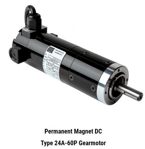
We define “SCR Rated” as a permanent magnet DC gearmotor that is designed to operate with an unfiltered SCR speed control while delivering similar speed and torque performance as a PMDC gearmotor that is designed to be operated from a filtered DC speed control or from a PWM speed control. SCR rated PMDC gearmotors or motors are designed to remain within their safe operating temperature range while delivering full rated torque over the entire speed range (when operated with an unfiltered SCR speed control). This is in contrast to PWM-rated PMDC gearmotors or motors which would need to be operated at reduced torque if they were operated with an unfiltered SCR speed control.
The majority of our standard stock 130V PMDC motors and gearmotors are rated for operation with a filtered speed control (FF = 1.0) at an armature speed of 2500 rpm. When operated with an unfiltered SCR control (90VDC off 115VAC), these stock motors will run at an armature speed of approx. 1725 rpm and would have to be proportionally derated. Hence, offering 90V or 180VDC “SCR Rated” gearmotors with an armature speed of 2500rpm allows the user to use the same gearmotor and gear ratio with either a winding for a filtered (PWM) or unfiltered SCR controls.

Form Factor for a DC speed control is a measure of the amount of current (ampere) filtering (smoothing) provided by the control to a motor. Form Factor cannot be determined until a motor and control combination are driving a load. However, most control manufacturers catalog their controls with a FF rating. Most small motor and control combinations exhibit FF= 1.0 to 1.05 with a filtered control and FF= 1.6-1.8 with an unfiltered control at rated torque.
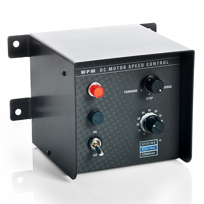
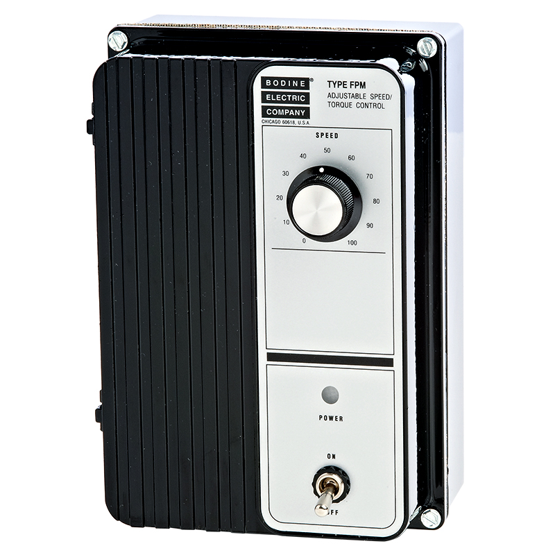
Bodine permanent magnet DC motors in this catalog are rated for continuous duty on 130 VDC, FF=1.05 current as supplied by Bodine type FPM and WPM controls. These motors and gearmotors can be successfully operated from unfiltered controls at FF=approximately 1.6, at speed not less than 1700 rpm. For intermittent duty operation, full nameplate torque may be available. The designers should test for each individual application.
Brush life will depend on current density, duty cycle, and environmental conditions. The absolute best estimate of brush life comes from data obtained while operating in the application. The brush inspection interval and process (if needed) may be included in the operating manual for the equipment which has the Bodine product installed. However, if such guidance is not available from the OEM, then we recommend that brush inspection be carried out at regular intervals of 4-6 months, or 1000 hours, depending on how many hours a day the motor operates. Assuming that all variables (i.e., current density, duty cycle, environmental conditions) are reasonably consistent, brush life should be fairly linear. It’s important to remember that one brush will wear more than the other if the motor only operates in one direction (i.e., CW or CCW), so both brushes should be checked for wear. Once you establish a brush wear rate for your unique application, you can adjust your inspection intervals accordingly.
Obtainable torque is the maximum output torque (peak torque) for a gearmotor. Gearmotors may be operated at these levels only for brief periods due to thermal or mechanical limitations.
The rated (nameplate) torques for stock gearmotors and motors shown in our catalog and on our website are for continuous duty operation. And while our standard/stock products are rated for continuous duty operation, they can also be used intermittently. Operation at loads higher than nameplate ratings is possible for short periods as long as there are rest periods for cooling. Loads higher than obtainable torque for gearmotors are never recommended. The temperature of the motor should be monitored during testing to make sure it is not overheating.
Obtainable torque is the maximum output torque (peak torque) for a gearmotor. Gearmotors may be operated at these levels only for brief periods due to thermal or mechanical limitations.
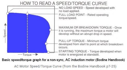
All Bodine stock gearmotors and motors are designed so that rated (nameplate) torque, shown in our catalog and on our website, is safe for continuous duty operation. These continuous duty stock products can be used intermittently, as well. Operation at loads higher than nameplate ratings is possible for short periods as long as there are rest periods for cooling. Loads higher than obtainable torque for gearmotors are never recommended. The temperature of the motor should be monitored during testing to make sure it is not overheating.
Obtainable torque is the maximum output torque (peak torque) for a gearmotor. Gearmotors may be operated at these levels only for brief periods due to thermal or mechanical limitations.
AC three-phase inverter duty (PP), three-phase synchronous inverter duty (YP), and some permanent split capacitor (PSC or CI) designs may be operated at adjustable speed with suitable controllers.
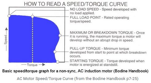
A synchronous motor is an induction motor that operates directly from AC power or from a variable frequency drive (VFD), and rotates at an exact multiple of the line frequency (or set speed). Common synchronous induction motor speeds at 60 Hz are 1800 RPM (4-pole) and 3600 RPM (2-pole). A unique feature of the AC synchronous motor is that there is no rotor "slip." The rotating magnetic field in the stator and the magnetic field in the rotor are "locked" in step as long as the load on the output shaft is within nameplate ratings.
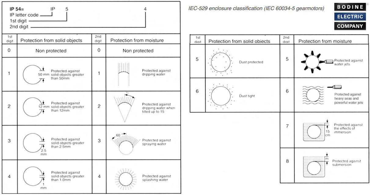
The IP (ingress protection) number is based on the international IEC system for rating enclosures. An IP-44 rating is roughly equivalent to NEMA 12 for dust and water resistance. IP-44 means that the gearmotor or motor housing is protected against solid objects greater than 1 mm, and against splashing water.
Our stock motors and gearmotors are typically rated IP-20 to IP-40. If you want to increase the ingress protection rating of our gearmotors and motors to IP-44, you can install our optional terminal box kits -- models 0984, 0985 or 0986. We also offer boot kits for our PMDC 24A, 33A and 42A motors.
Self locking refers to the tendency of some gearing to resist movement when the gearmotor is at rest and the load is attempting to move. An example is a load on a conveyer belt trying to drive the system backwards. Right angle gearheads with ratios greater than 20:1 are often considered to be self locking.
Parallel shaft gearheads and right angle gearheads with low ratios are generally not considered to be self locking. Right angle gearheads with ratios greater than 20:1 are often considered to be self locking. They will resist movement up to their torque rating. As the gearing nears the end of its useful life or if it is subjected to overload conditions, it may wear to the point where it is no longer self locking. Self locking gearing is not a recommended method for preventing movement in applications.
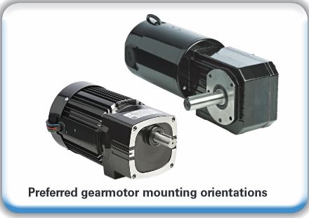
Motors without gearing and K-2 gearmotors may be operated in any position. Standard Bodine gearmotors are designed for universal horizontal mounting with the motor portion or the drive shaft horizontal. Other mounting positions are possible, depending on the gearmotor type (and lubricant). Some gearmotors are oil lubricated. If these gearmotors are mounted in a position other than horizontal, the oil might find its way out of the gearbox as the motor shaft or the shaft seal wear out over time. When in doubt, please consult our technical support staff in Northfield (Chicago area). You can e-mail us at info@bodine-electric.com.
A motor designed for 60 Hz operation will run at 5/6 rated speed on 50 Hz. This can be of concern for totally enclosed, fan cooled (TEFC) motors or gearmotors. For example, a motor rated 1700 RPM on 60 Hz will run at 1400 RPM on 50 Hz. When the motor fan runs slower, the motor winding will receive less then the expected cooling.
Bodine 60 Hz permanent split capacitor (PSC) "Cl" motors will run hotter on 50 Hz, and typically require a capacitor change and derating. The motor temperature should be monitored during testing to make sure it is not overheating. Bodine split phase (or "Sl") motors and gearmotors that are rated for 60Hz should not be operated on 50 Hz because the internal centrifugal cut-out switch will not cut out correctly and might damage the start winding. Consult the factory for a 50Hz solution.
Operation of more than one motor from a single control is not normally recommended (PMDC or BLDC). However, when cost is a primary concern, a multiple motor/single control system with either permanent magnet motors and control or 3 phase motors and control may be successfully implemented. More than one AC three-phase, inverter duty motor/gearmotor may be operated with a single AC speed control (=inverter, = adjustable speed drive), as long as the sum of the motor currents does not exceed the rated output current of the control. Motor speeds should not fluctuate as long as the motors are not overloaded and the sum of the motor currents does not exceed the rated output current of the control.

Radial load is a force pushing or pulling the side of the output shaft. It is shown in the diagram (at right) as Fr. Exceeding the allowable radial load for a motor or gearmotor will cause premature wear of output shaft bearings and gearing and could cause the shaft to break. Fr may be the result of a weight on the shaft, belt tension or torque transmitted through a belt, chain, gear, or certain flexible couplings. Our catalog shows the permissible radial load for each motor and gearmotor. In calculating these values, the following assumptions were made:
- The radial load is in the worst case direction, i.e. pushing or pulling the shaft sideways.
- The motor or gearmotor is delivering rated torque.
- The radial load was applied at distance "d" from the hub or mounting surface. Higher radial loads may be applied closer in on the shaft. Lower radial loads are permitted further out on the shaft.
Flexible couplings are often used to avoid radial load. Most flexible couplings are designed so that they do not transmit radial load, however this should be verified by the coupling manufacturer.

Axial load is a force on the output shaft into or out of the motor or gearmotor. It as shown in the diagram (at right) as Fa. Exceeding the allowable axial load for a motor or gearmotor will cause premature wear of output shaft bearings and gearing.
.gif)
Most of our standard products are fully coated with a black finish on all exterior surfaces. Some stock gearmotors are partially painted, and some custom OEM products might not be painted at all (dependent on the application and operating environment). For a given motor or gearmotor type, the motor components have the same physical dimensions, but paint or coatings on external surfaces will add to the overall dimensions. The paint thickness is not reflected in the dimensions on our online CAD drawings, and it could be up to 0.006 inches thick on each painted or coated surface. Different components may feature different surface coatings: we typically powder coat our castings, some parts are anodized, and stators with exposed laminations are either wet painted, or have an e-coat surface finish (e.g. 22B, 30R, K-2 stators).
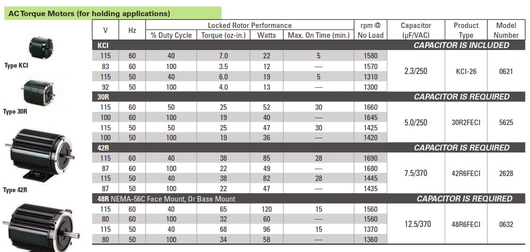
Bodine offers AC induction motors that are impedance protected - we call these types of motors AC Torque Motors. These motors are ideal for tensioning applications because they can operate in stall mode without overheating. Torque motors feature: Higher starting torque at lower speed and lower running torque, and the ability to run in stall mode without Overheating (impedance protection).
What does "impedance protection" mean? It means that the motor winding temperature stays within its thermal limits when it is stalled. If the motor needs to be operated in 100% stall mode, then the operating voltage has to be reduced to x% of the rated voltage (see our stock catalog S, page 20 for details).
Application Example: Tensioning a web, wire or film in an unwind or rewind application. In these types of applications, the motors act like an "electronic spring".
It does not matter how voltage is supplied to the torque motor, as long as the average voltage supplied is per the motor’s specifications. Some options that you can use are: a step-down transformer or an inverter with single-phase output. See our stock catalog S, page 20 for reduced voltage specifications.
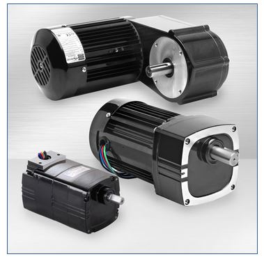
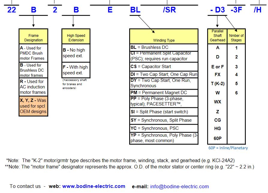
The winding type is shown on the heading of each selection table for each product. It is also included in the Bodine Frame Type as a 2 letter code. On a motor, it is the last 2 characters. For example, Bodine Frame Type 42A5BEPM is a "PM" or Permanent Magnet. On a gearmotor, it is the 2 characters before the dash (-). For example, Bodine Frame Type 34R6BFCI-W2 is a "Cl" or Permanent Split Capacitor Motor. The Technical Discussions at the beginning of each section in our catalog provide more information on the characteristics of the winding types in the section.
We recommend this custom design feature for applications where the machine design requires high starting torque. These special AC induction motors with torque core rotors deliver: Higher starting torque at lower speed and lower running torque.
The brushless DC (BLDC) motors/gearmotors are the quietest of all of our technologies. They are then followed by the AC motors/gearmotors – specifically the three phase and permanent split capacitor motors first and followed by the split phase motors. The Permanent Magnet DC (PMDC) motors will run the loudest of all three technologies. Bodine values itself on high quality, quiet motors and gearmotors. “Loud” is relevant, and application-specific, but all of our motors and gearmotors, in all three technologies, should run efficiently and quietly.
The standard brushless motors/gearmotors have a 60 degree commutation. Some BTO (Built-to-Order) motors/gearmotors have 120 degree commutation. If in doubt, please contact our Inside Sales team with your serial number.
The maximum backlash for our standard/stock parallel shaft (helical/spur) gearmotors is 3 degrees. The backlash also depends on the number of gear stages and the gearing type. Some of our parallel shaft gearheads use only helical, some use spur and helical, and some use Nylon and steel gear combinations. In general, we cut and finish all our gearing to AGMA 9 specifications, and we typically see a backlash of 1.5 degrees or better in most of our stock products. Bodine also offers planetary BLDC and PMDC gearmotors that have a standard backlash of < 60 arc minutes.

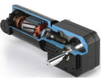
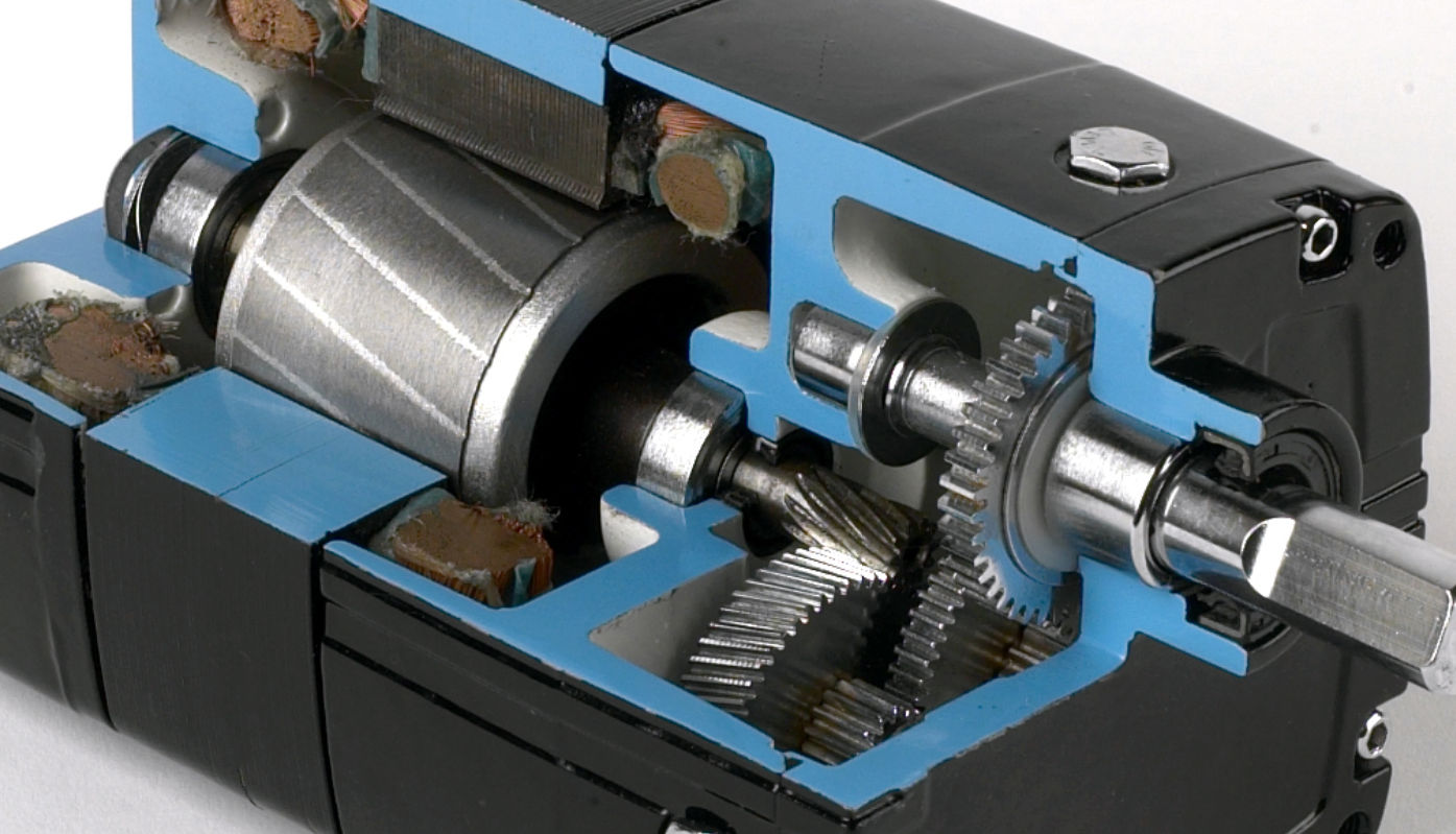
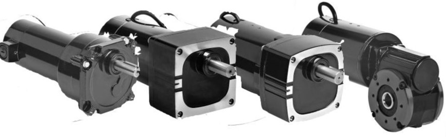
Gearmotors are ideal for applications that require high output torque in the smallest possible drive package, or when the motor output speed needs to be reduced. Their high torque-to-size ratio makes them the ideal drive solution for tight spaces, or when the overall machine design needs to be optimized for the smallest possible motor footprint. The inherent benefit of integral gearmotors is that they function as torque multipliers and speed reducers, requiring less motor power to drive a given load. The gear housing design, the gearing type, gear lubrication, and the specific mode of integration all affect the gearmotor performance, and application suitability.
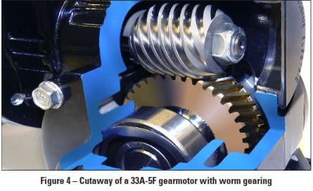
Brushless DC (BLDC) gearmotors are typically quieter than PMDC gear motors or inverter-duty AC three-phase gearmotor and motor designs. PMDC gearmotors have carbon brushes that continuously “rub” on the commutator of the motor armature. This interaction, along with the DC power from an unfiltered SCR or PWM speed control can result in audible noise. Similarly, inverter-duty, variable speed AC motors and gearmotors emit some noise created by the PWM voltage supplied to the motor from the inverter (PWM speed control). Gear housing style and design, as well as the number of gear stages can also affect overall noise emitted from the gearmotor. Worm gearheads (right-angle gearmotors) are generally quieter than inline or parallel shaft gearmotors due to the differences in gear geometry and how the gear sets interact.
Download our informative Gearmotor Selection and Application Guide – then consider these basic design criteria to determine which gearmotor is right for your application
- Intermittent vs. Continuous Duty
- Speed and Torque
- Gearhead Life
- Output Torque
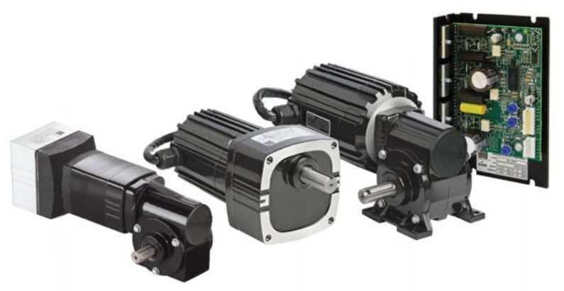
- PMDC vs BLDC or AC power
- Mounting Orientation
Inverter-duty gearmotors (and motors) feature variable speed, AC three-phase motor windings that are designed with a special winding insulation system to protect them from potential voltage spikes or corona damage caused by the AC “inverter” PWM speed control (Variable Frequency Drive / VFD). The special inverter-duty windings meet NEMA motor standard MG 1, Section IV, Part 31. In general, AC three-phase gearmotors and motors are more efficient than their AC single-phase counterparts, they are more compact, and provide higher output torques in the same size package. In addition, these variable-speed AC gearmotors and motors don’t require brush replacement or brush maintenance. Typical Applications are conveyor systems, food processing equipment, factory automation, pumps, lifts and packaging equipment.